Friday, December 30, 2011

ARM for Hobbyists

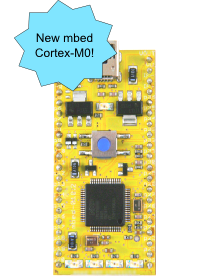
M0 mbed from mbed.org
ARM chips have gained a foothold in hobby electronics that I suspect will become fairly significant by 2015 or so.

Certainly some projects (several of mine included) will benefit from more RAM, larger program space, faster clock speeds, and 32-bit processors.

What's required for widespread uptake of ARM are a combination of free tools with libraries that simplify programming and low cost development boards that make prototyping easier.

  • Leaf Labs began providing an Arduino-derived IDE for their Arduino-compatible STM32 ARM-based boards some time ago. The Maple Native has been promised for quite awhile but nothing yet.
  • The mbed M3 and M0 dev boards with online compiler have been around for a few years now and are growing in popularity. The DIP package makes for easy breadboarding. The library is truly stellar and there's a big community and many user-written objects. An RTOS is available. Web-based compilation is quite fine if you're not in the field.
  • The LPCXpresso is a bit faster than the mbed at 120MHz and comes with a free IDE and features a DIP form factor, too.
  • To get down to the bare metal, CMSIS is a cross-platform library from ARM that abstracts the ARM core capabilities. As far as I know, vendors supply peripheral libraries. STM has a standard peripheral library, for example. DSP libraries are typically available, too.
  • Arduino and Atmel have teamed and announced the Due featuring a SAM3U, a 96MHz ARM Cortex M3. Still waiting on this (7/2012) and actually we've been waiting for quite some time. The big issue I see is that Arduino libraries don't even come close to taking advantage of all a typical ARM MCU's capabilities so presumably enhanced capabilities are in the works, but that is just my assumption.
  • The Wiring project (from which Arduino descended) plans to introduce STM32 ARM compatibility at some point. I've been waiting to see the home page announcement change for quite some time, now. Leaf Labs is working with Wiring now.
  • CooCox is an IDE, peripheral library, and set of tools intended for programming across multiple ARM families, with a few supported so far (7/2012). As ARM peripherals differ across families, this project is quite promising but like others, is dragging on.
  • Among a slew of hobbyist-unfriendly QFP packages, one ARM vendor, NXP, is supposedly going to release a 28-DIP form factor Cortex M0, the USB-capable LPC1114FN28 but I've been waiting for this to show up for almost a year now (7/2012). NXP offers M0s in SOIC and TSSOP form factors as well.
  • There are more than a few low cost dev boards out there. Too many to list, in fact.
Not that ARM is the only 32-bit, high performance game in town but I've become very interested in the platform in the last few months. I know this isn't a comprehensive list. If you know of other ARM-based development hardware/IDE platforms I'd love to hear about it.

Bottom line: your best bet is the mbed platform, I think. The library capabilities are awesome and you get a lot of community support. It's a huge step up from the Arduino paradigm many of us are used to. While we wait and wait for the Arduino Due, Wiring, CooCox, Leaf Labs solutions seem viable.

Otherwise you're left to coding your own stuff using CMSIS and vendor libraries. It's more painful and you're basically stuck with a particular vendor, maybe even a particular family.

Coding an ARM is quite a bit more complex than coding an 8-bit AVR and that may be why we haven't seen a clear open source winner emerge yet.

Friday, December 23, 2011

Pololu Goodies

Happy Holidays to those who celebrate!  Despite my fear of sounding like an advertisement, I love Pololu. Great people; they have always been friendly to me, and they come up with some really cool robots and components.

A few weeks ago I received a package with my Black Friday spoils and it was just like Christmas had come early.

Can't wait to try some high speed line following...

Mmmmm... tank treads.
Besides the above, I also ordered a 9DOF IMU and have implemented an AHRS using Pololu's sample code running on an ATmega328P.

Thursday, December 22, 2011

Jingle Bells


Ok, it's been done before, but why let that stop me?

Through the holidays, when you visit my blog, here, you'll add to the household festivities because a little bell in my office will jingle. And also, an angel will get its wings.

This version is a PC and Propeller-based holiday kludge-o-rama. Here's how...

Friday, December 16, 2011

Magnetometers and Motors

Test rig for current measurement
Now that I've got a mechanism for measuring motor current, it's time to try and quantify the effects of motor magnetic field on magnetometers.

Data Bus was cursed by Compass heading deflection earlier this year and I never discovered its cause. The error observed was on the order of 20 degrees or more.

As part of my ongoing work to get ready for the just-announced Sparkfun AVC 2012, I want to see if I can correlate motor current and magnetometer readings using a Honeywell HMC5843 3-axis magnetometer.

Friday, December 9, 2011

RadioShack? Yes.

I've been visiting Radio Shack stores since I started dinking around with electronics in high school in the 80's. I'm not affiliated with them, but I've always been a loyal customer. Though I've heard many hobbyists dis them over the years, at least they've always had components on the shelves.

But nothing like this!

Arduino and Parallax gear including a Propeller board!

The venerable Forest Mims III books are back and better than
ever along with other promising titles

I almost missed this entire endcap of Arduino,
Make and Parallax goodies
Propeller boards, Arduino boards, Make kits, gyros, GPS, and on and on. Radio Shack is carrying a lot of really great hobbyist/roboticist/maker/electronics nerd gear. Go check it out.

Never have I been so excited to visit a Radio Shack since the days of blue Archer packages and speech chips hanging by the dozens.

Radio Shack has been saying recently that they're committed to DIYers. If this doesn't convince you, nothing will.

Friday, December 2, 2011

Constructing RoboTurkey


Here are some construction details for RoboTurkey. Warning: lots of pictures and a video, to follow...

Friday, November 25, 2011

Sparkfun AVC 2012

Data Bus is back and he's pissed.
Last April, Data Bus experienced crushing, embarrassing, humbling defeat. For six months, he's been nursing his wounds and stoking the fire in his belly while his thirst for victory has grown insatiable. 

It's time.

I'm getting an early start on the 2012 Sparkfun Autonomous Vehicle Competition, greatly aided by the fact that I'm not starting from scratch. I'll chronicle the revisions over the next six months.

Thursday, November 24, 2011

Happy Thanksgiving

A message to you from the newly completed RoboTurkey:


RoboTurkey's actual name is Oscar (all Thanksgiving turkeys are named Oscar in our family). At random intervals, he either moves his head around, flaps his wings, or speaks while moving his wings for emphasis. He simultaneously moves his beak while playing back audio clips of my daughter talking.

 Here are some specs and info:

  • Wings and tail crafted by my 2 year old daughter
  • Plays back 8 phrases spoken by my daughter and recorded to a 2GB microSD card
  • Parallax Propeller on one of my miniProp boards
  • Software written in SPIN and PASM
  • LM386 audio amplifier with gain of ~20dB
  • Head, beak and wing movement controlled in parallel
  • 3 hobby servos I had laying around
  • 6 AAA batteries
  • NCP1117 LDO 5V regulator
  • Cookie tin from Goodwill
  • Feather boa, lots of craft sticks and hot glue from Hobby Lobby
  • Plays back audio from microSD
I'll post up build details in the near future.

Source

https://github.com/shimniok/roboturkey

Monday, November 21, 2011

Black Friday Deals

Pololu is again doing a black Friday sale with lots of great deals and thought you might want to know.

I am going to try to be one of the first 50 people to get a 3pi robot, and I have a shopping list of other goodies I'd like to get like a $30 9-axis IMU.

Last year I scored a baby Orangutan, a couple of IR sensors, some nice voltage regulators, and a few other things.

Friday, November 18, 2011

Cheap Logic Analyzer SMD Clip Hack

Cheap ebay clip, center, Selae Logic Analyzer clip, right

Want cheap SMD clips for your logic analyzer? One of my readers, Nemo, submitted a nifty hack to convert budget clips (above, middle) for use with typical female logic analyzer leads (above left).

Friday, November 11, 2011

Electronic Candle with a 555 Timer

Pokey my Trinity-style firefighting robot likes to blow out candles. It's his job. Whenever I demo Pokey at robotic events, I don't dare light a real candle lest I burn the place down.

Holding a flashlight for Pokey to track lacks drama, so here's a DIY electronic candle that you can actually blow out. You can build this yourself on a breadboard or on a simple home-etched pcb.


Friday, November 4, 2011

Road Testing an ARM LPC2101: Part 1

I was graciously invited to participate in the Newark Product Road Testing Program and I'll be road testing two ARM microprocessors. First up is the NXP LPC2101, recently added to Newark's offerings.

While I relay my experiences, my hope is to make it easier for you, gentle reader, to jump into the wonderful world of ARM along with me. ARM processors have their place in robotics and electronics, can be inexpensive like this LPC2101, and can be very powerful. (You can find more NXP ARM processors from Newark here)

I hope to show that you don't need expensive breakout boards or cumbersome evaluation boards, and you can use free toolchains. So... let's get started...

Tuesday, November 1, 2011

Thompson Robotics Expo 2011

This past Saturday, my daughter and I had fun at the Thompson Robotics Expo up in Loveland and we set up a table for SHARC to demo Data Bus and Pokey.


Pokey, my Trinity-style firefighting robot, ran some demos where the little robot used rudimentary machine vision to search for a 'candle' (flashlight), drive forward to the white floor marker, and turn on the fan to 'blow out' the candle.

Friday, October 28, 2011

Measuring Motor Current

I need to measure the current going through brushed DC motors. One of the ways to do this is to use a shunt resistor, a low-value, precision resistor. Measuring the voltage drop across the resistor, one can calculate the current through the resistor.

I decided to make my very own, very simple, shunt resistor breakout board. It connects between the battery and Electronic Speed Controller (ESC) or other motor driver. 


A header is included to measure voltage across the battery and voltage drop across the resistor either with a DMM or a microcontroller.

DMM test clips attached
I quickly drew up the design in Eagle, used toner transfer method and etched the board, soldered everything together and voila, simple current measurement. 

Pretty simple circuit board, eh?

0.001 ohm, 1%, 3W = 50A+ (WSR31L000FEA)
The resistor is 0.001 ohms so 1mV = 1A (it's a Dale-Vishay WSR31L000FEA). My DMM has precision to 0.1mV, thus 100mA here. I selected a resistor with sufficient power handling to measure over 50A continuously.

So what the heck am I going to do with this thing?
  • Measure RC airplane propeller load on motor
  • Calculate battery internal resistance
  • Plot relationship between motor current and compass distortion
  • Calculate remaining battery capacity on an autonomous robot
  • Overcurrent protection
  • Create a digital ammeter with an MCU and LCD display
Some add-on hardware is needed to interface with a microcontroller. The AttoPilot shunt boards use a Texas Instruments INA-169 for amplifying voltage drop across the shunt to a suitable range for an analog to digital converter. (While I am using the simpler board above for bench testing, I decided to get the AttoPilot board for use on Data Bus)
AttoPilot current/voltage sense board
One has to be careful, of course, that the shunt presents substantially less resistance than the load. Some motors have very low resistance windings. For those cases, a hall effect sensor like the Honeywell CSLA2CD seems like it would do the trick.

Friday, October 14, 2011

Why The Wrights Flew First

Orville demonstrating the flyer
to the U.S. ArmyFort Myer, Virginia
September 1908. Photo: by C.H. Claudy.
(Source: Wikipedia)
At the time the Wright brothers achieved the first powered airplane flight at Kitty Hawk1, the field of aeronautics had been buzzing with activity for years (perhaps not unlike the present DIY robotics community).

Why did they succeed where others failed? 

Tuesday, October 11, 2011

The miniProp Contest Begins

miniProp. Win one.
It's time. Head on over to the Bot Thoughts facebook page and enter to win a miniProp, a Parallax Propeller on a DIP form factor with built in regulator, eeprom and crystal. Free IDE from Parallax, lots of community support, 8 cores (cogs), deterministic timing, easy to learn assembly, and more.

Next Tuesday I'll pick the winner at random out of the list of folks who comment on or like the contest post. Good luck!

Friday, October 7, 2011

Win A Propeller Board!

Aww... so cute!
It's small, it's standalone, it's purple, and it's a Parallax Propeller, aka an experimenters dream. I designed this breakout board and I'm giving away a fully populated board to a lucky reader! I call it the miniProp board.

The Propeller has 8 cores (cogs) that operate together in perfect lockstep. The chip has perfectly deterministic timing and really simple assembly language. Writing device drivers on the Propeller is truly a piece of cake. And when you're done you have several cogs left to do lots of interesting things besides.

Friday, September 30, 2011

I2C: mbed reading from Arduino

Quite some time ago, I covered how to get two AVRs talking to each other using the I2C protocol.

Here's how to get an mbed and AVR talking with I2C, with the mbed acting as Master and the AVR acting as Slave.

Let's say you want the mbed to query the Arduino to respond with 4 bytes of data.

The mbed will write an address byte with the read bit set, using the Arduino's address, and then it'll request to read four bytes.  The protocol exchange looks like this:

1. Send a start sequence
2. Send 0xC1 ( I2C address of the slave with the R/W bit high (odd address)
3. Read data bytes from slave
4. Send the stop sequence.

(source: I2C Tutorial)

On the Arduino, call Wire.begin(7), where 7 is the Arduino's I2C address. That tells the Arduino I2C peripheral what messages to listen for. Then call Wire.onRequest() specifying a handler function that is called when the master requests data.

void handleI2CReceive(int numBytes)
{
  char command = Wire.receive(); // pretty much just ignore the command

  return;
}

void handleI2CRequest()
{
  byte data[4];

  // the code below just sends
  // data from the global variable
  // box, a struct with 4 char members
  //
  data[0] = box.x1;
  data[1] = box.y1;
  data[2] = box.x2;
  data[3] = box.y2;
  
  Wire.send(data, 4);
  
  return;
}

void setup() {
  Wire.begin(I2C_ADDRESS);

  box.x1 = box.x2 = box.y1 = box.y2 = 0;

  Wire.onRequest(handleI2CRequest);
  Wire.onReceive(handleI2CReceive);
}
On the mbed, use the "raw" I2C library's start(), write(), read(), stop() methods and manually set the address. Take the I2C slave address, left shift once, and set bit 0 high to indicate a read operation. Then read four bytes. Like this:

        cam.start();
        data[0] = (0x7<<1 | 0x01); // send address + !write = 1
        cam.write(data[0]);       // send address
        data[0] = cam.read(1);
        data[1] = cam.read(1);
        data[2] = cam.read(1);
        data[3] = cam.read(0);    // don't ack the last byte
        cam.stop();

This only works when the slave has one "register". Suppose you have an Arduino that can respond with one of several ADC readings. The protocol exchange would first include the master writing the desired register number to the slave, sending another start, then reading the data. The Arduino would have to accept the register number and store that until the next read request, responding with the correct register's value.

Friday, September 16, 2011

AVR Low Power

My RC airplane Lost Model Alarm (LMA) runs off a tiny CR1225 50mAH battery so low power operation was a must. Here's how to save power with your AVR or Arduino project.

Monday, September 12, 2011

XV-11 Imaging Sensor Revealed!

Image from Random Workshop,
blog of XV-11 Hacking Guru  Hash79
The XV-11 LIDAR has finally been completely cracked open.

Hobby roboticists are on the cusp of DIY, sophisticated, low cost, obstacle detection.

The XV-11 uses a laser-based "radar" that can map out the environment allowing the vacuum cleaner to navigate its environment avoiding obstacles like chair legs, sofas, cats, and more. With this kind of sensor your robot can also detect which room it's in.

Well, thanks to the winner of the Open Lidar Project, XV-11 hacking contest, now we can build our own: all the chips including the imager are known. Follow the link to find the details.

Friday, September 2, 2011

A Review of Free Windows Gerber File Viewers

When you send off your latest PCB design to a PCB fabrication shop you'll typically send Gerber files. You probably want to perform a final proof-read of your design, so you'll need a Gerber file viewer to view your files graphically. If you're cheap like me you want a free Gerber viewer. Here's a brief review of truly free Gerber file viewers for Windows.

Friday, August 19, 2011

DIY Lost Model Alarm for RC Plane

My Champ with bush tires
Earlier this summer, I bought and quickly lost a Hobbyzone Champ ultra-micro RC plane. I needed a Lost Model Alarm. Correction: I need to make my own LMA!

On my maiden flight, wind blew the light, 1.5-ounce plane away and I lost sight of it over the trees.

I'm not the only one. Many other Champs, and maybe other ultra light UM (ultra micro) planes, like those from Parkzone, have been lost by newbie pilots. (Some neighbors found mine, thankfully).

Friday, August 5, 2011

Dorkbot PDX Circuit Boards Delivered

The printed circuit boards I recently ordered through DorkbotPDX arrived!  My very first professionally fabricated boards!


To my eye, they look great. Nicely plated pads, solid dark purple solder mask, nicely done thin traces, and the silk screen looks really good, especially considering how small I made it.


Friday, July 29, 2011

GPS Signal Reception

While I was working on Data Bus I ran across a few interesting behaviors in GPS signal sensitivity.

source: geocaching.com
You may recall that Data Bus V1.0 uses a Pharos iGPS-500 GPS module, based on a SiRF StarIII chipset. I got it for under $20 through a vendor on Amazon thanks to a tip from a forum on LetsMakeRobots.

First, I noticed that the closer the GPS device was to the chassis electronics, particularly the mbed microcontroller, the worse the signal reception. So I put it up on a mast about 30cm from the main electronics.

Second, I discovered that whenever I placed the GPS on a small sheet of metal, signal reception increased by 5 to 10dB for all satellites in view. I am guessing that the metal acts as some sort of ground plane enhancement to the metal underneath the ceramic antenna on the module. Feel free to offer explanations in the comments.

On Data Bus, I placed the module on a square sheet of tin about 4" square and consistently got really good reception: 7-9 satellites in the basement, for example. Of course the accuracy still suffered in adverse conditions. Such as, oh, I don't know... sitting on the starting line at the Sparkfun AVC?!

Third, I attempted to add a CMUcam V1 with an Arduino acting as a bridge between TTL serial and I2C and whenever I turned on these devices, the GPS reception tanked. Half the satellites could no longer be seen, the other half were so weak I could hardly get a 2d lock let alone 3d. The cause? I don't know. RFI/EMI? Or dirty power supply? Haven't researched that yet.

What I do know is that mounting a GPS sitting atop a 30cm mast on an 1/10th RC truck makes for some craptastic handling.

Thursday, July 28, 2011

mbed.org now supports version control

After beta testing, mbed.org has released version control. That is a huge step forward for the usefulness and usability of an already excellent, powerful, cloud-based IDE. I can't wait to give the new feature a try!

Friday, July 22, 2011

Getting Started With ATtiny13, ATtiny85

I've been wanting to play with 8-pin AVRs for awhile and finally got around to it.

Here's what's involved in downloading code to an ATtiny13, ATtiny85, and other AVR microprocessors. In this example, the ATtiny13 resides on a solderless breadboard for prototyping though you could simplify and (shameless promotion) buy my ATtiny breakout boards. :)

Pinouts For In-System Programming

We'll use In-System Programming (ISP), a feature on all the AVR ATtiny and ATmega MCUs (as far as I know). It's a serial protocol, but unlike RS-232, there's a clock signal along with the TX and RX signals.

AVR's ISP cables have 6 pins: reset, clock (SCK), data to the chip (MOSI), data from the chip (MISO), as well as Vdd and GND. Follow the diagrams on my guide for AVRISP Pinout for 8-pin, 14-pin, 20-pin ATtiny and ATmega328P.

AVR Programmers

You can use Pololu's inexpensive USB AVR programmer, PGM03A, as I did. It's a great programmer and I used the older version of it for a few years before upgrading. Plug the 6-pin ribbon cable into the programmer, then use jumper wires (I use these jumpers from hacktronics.com) to connect to the ATtiny on the breadboard. Add power (the newer PGM03A has 5V/GND pins) and you're ready to start programming. I've also used a JTAG ICE MkII which is expensive but has worked very well, too.

ATtiny breakout target board
As mentioned (shameless promotion) my eeZee Tiny includes AVRISP header, caps, reset switch and pullup. Add power and start programming. Get the kit from my store on Tindie.

Choosing an IDE

I decided to try AVRstudio 4 for the first time and Pololu has a tutorial on using AVRstudio with their programmer. It's easy to use an AVR programmer/debugger, as you might imagine. AVRstudio has nice debug features that accelerate troubleshooting in certain circumstances.

I'm currently using Eclipse with AVR plug-in as my IDE as the editor is significantly better. To use the Pololu AVR Programmer, Configure plug-in that you're using an AVRISP Mk II on whatever serial port is allocated to the programmer.

Blink an LED on ATtiny

The embedded programming version of hello world, as you probably know, is blinking an LED. We'll cast off the fluffy, protective blanket of Arduino and try this, AVR-style. It's not as easy, but it's not very hard either.

#include <avr io.h>
#include <avr interrupt.h>
#include <avr sleep.h>
#include <util delay.h> 

/** ATtiny13 hello world; blink LED on Pin 2
 *
 * Michael Shimniok - http://www.bot-thoughts.com
 */
int main(int argc, char **argv)
{
 DDRB |= _BV(3);  // PB3 (pin2) as output
 while (1) {
  PORTB |= _BV(3); // turn on LED
  _delay_ms(500);
  PORTB &= ~_BV(3); // turn off LED
  _delay_ms(500);
 }
}

Additional Tips

To avoid programming glitches, keep the ATtiny13 clock speed up (9.6MHz, maybe even disable CLKDIV8) or reduce the programming speed.

The ATtiny13 is has very little flash or RAM but you'd be surprised at what you can do with it. It does have a timer with PWM modes and a multi-channel ADC. The form factor is, well, tiny, and the 8-pin AVRs are a great addition to the geek arsenal. I've been using 8-pin and 14-pin ATtinys quite a bit lately.

Did this help you? If so, do me a favor and share via redit, twitter, Google+, etc. Thanks!

Friday, July 1, 2011

Cheap But Excellent Batch PCB Fabrication

I was reading a recent blog post on Life of Kenneth and saw a reference to DorkbotPDX batch PCB fabrication named Laen has been coordinating for some years now. It's know nown as: 

OSHPark.com

The printed circuit boards are made in the USA, the costs are $5/sq in with no setup fee for two-layer PCB designs. Four layer boards run more but still quite affordable. You order PCBs in sets of three. And the soldermask is a nice, custom purple! ooooo....!

Image from DorkbotPDX pcb fabrication ordering site
I've been using DorkbotPDX now OSHpark for a year or so now and have done probably a dozen printed circuit board layouts. Every one has come back with excellent quality. The silk screening is very detailed, the plating is fantastic, the soldermask are always right on. That's what you get when it's made in the USA. 

My Toshiba Camera Breakout PCB

And you get fast turnaround (in the US), usually within a couple weeks. He's now doing so much volume that he's sending 2 or more boards per week to the PCB fabrication company.

Home DIY PCB Fabrication top, DorkbotPDX bottom
Laen reports a very low error rate of about 1 in 10,000. Can't say enough good things about this service and I often prefer to wait a few weeks and just have the board fabricated than etching my own single-layer PCB at home.
MiniProp: Propeller breakout. QFP 0.6mm pitch
I've now gotten heavily into SMT designs. I've done PCBs with 0.5mm pitch QFP chips, 0603's, tiny 0.032" lettering (0.4" is better), SOICs, 12mil traces, etc. All the boards come back beautifully.

ARM LPC2103 breakout PCB. QFP 0.5mm pitch
Ultra-Micro Lost Model Alarms

SMT version of AVRcam. QFP 0.6mm pitch


Friday, June 24, 2011

TGIMBOEJ #2

With all the craziness of the AVC, I totally forgot to post about the second TGIMBOEJ I received. It was chock full of all kinds of neato bits.

Added: Some memory cards, junked micro helicopters, various vintage passives and transistors, switches, hair drier blower, 6v wall wart

Took: micro heli controller, some jumpers, mini embedded multimeter thingy, binding posts, and a couple other things I forgot about


Lots of great stuff still in there.

Tuesday, June 21, 2011

Tools: Equation Editor (take 2)

[let's try this again...*ahem*]

A couple months ago I found this neato equation editor/creator that generates a nice equation image. Handy for us technical bloggers. I've already used it on several posts. Enjoy!

http://www.codecogs.com/latex/eqneditor.php

Sorry about the mishap yesterday.

Friday, June 17, 2011

Generate a Clock Signal with AVR ATmega

AVR-generated clock signal
Several times lately my MCU needed to generate a clock signal to interface with a device, such as a camera, or a serial interface on an analog to digital converter (ADC).

Rather than bit-banging the clock signal, let the MCU's timer hardware do the work, freeing up cycles for real code.

Here's how to generate a simple, 50% duty cycle pulse train, aka clock signal, using an AVR MCU. For this experiment I used an ATmega328P but any of the AVR chips that support a 16-bit Timer1 should do.

I wanted a 500kHz clock signal. To generate it, the MCU must toggle an output pin, PB1 aka OC1A at 1MHz, or 1/16 the MCU's 16MHz clock, for a total period of 2us (500kHz).

Timer1 provides a mode called Clear Timer on Compare Match (CTC). The timer register, TCNT1 counts from 0 up to the value in the Output Compare Register, in this case OCR1A (to go along with the OC1A output). When TCNT1 == OCR1A, the MCU resets TCNT1 and starts counting again.

Ok, let's get started with the code.

Though we probably don't need to, why not initialize the counter:

TCNT1=0;

To run the timer at 1MHz, we need to divide the MCU clock by 16. Using a prescaler value of 1, we simply set the output compare register to 15, since the timer counts from 0-15 or 16 ticks.


So we come up with:

OCR1A = 15;

Note that we could also have used a prescaler value of 8 and an OCR1A of 1.

Now it's time to set some mode bits. The AVR has three Timer/Counter Control Registers for timer 1: TCCR1A, TCCR1B and, you guessed it, TCCR1C.  In TCCR1A, two bits control the behavior of OC1A when the timer matches OCR1A. Those two bits are COM1A1 and COM1A0. When set to 01, OC1A is toggled when there's a compare match.

TCCR1A |= (1<<COM1A0);

To tell Timer1 to operate in CTC mode, we set bits WGM13, WGM12, WGM11, WGM10 across two control registers. Actually for CTC mode, WGM12=1 and the rest are 0 (initial value on powerup)

TCCR1B |= (1<<WGM12);

To configure Timer1 prescaling, set bits CS12, CS11 and CS10 in TCCR1B. For no prescaling, use 001, respectively. That is, set CS10=1

TCCR1B |= (1<<CS10);

The only thing left to do is to enable the OC1A (PB1) pin for output

DDRB |= _BV(1);

Putting it all together, here's the code that generates the clock signal in the picture above.

TCNT1=0;
OCR1A = 15;
TCCR1A |= (1<<COM1A0);
TCCR1B |= (1<<CS10) | (1<<WGM12);
DDRB |= _BV(1);


Finally, if you want to sync your code to the rising and falling clock edge, check the TIFR1 register for the OCF1A flag:

if ((TIFR1 & _BV(1)) == _BV(1)) {
// do something here
}


Or, you can sync your code to a high or low clock value by reading PB1 from the PINB register.  The MCU can also be set up to call an interrupt service routine whenever there's a match.

Friday, June 10, 2011

Fast Robots are Hard to Build

Back when I was delusional enough to think I should try to actually win the 2011 Sparkfun AVC, I realized I needed a fast robot. The 2010 winning time worked out to a speed of something like 5mph while the 2011 winning speeds were a little over 10 mph, about what I was aiming for, myself.

I wonder what the winning speed will be in 2012, assuming no changes to the rules? 20mph? 30? more? Several of the robots entered this year were capable of running at more than 30mph. A Traxxas Rustler can peak out at 35mph with a 7-cell battery and a large pinion gear.  The VXL version with LiPo and brushless motor can run 60mph.

But, speed without proper control simply won't get it done.

One of my big goof-ups in building Pokey, the firefighting robot, was that I didn't carefully think about speed, timing, and sensor range. The faster your robot is, the more carefully you need to deal with timing, speed, physics, and sensor range.  Here's what I learned from that failed experiment.

Sensor Range

My AVC robot was originally designed to be speedy (10-20mph), but the 2011 AVC incorporated giant barrel obstacles to detect and avoid.

Imagine dodging boulders on the highway while driving 100mph--in a fog with 10 foot visibility! No way. Sensor range has to be long enough to allow the robot to react to obstacles.

I considered several long range sensor options.  To illustrate the issues: one Sharp IR ranger has a range extending to 150cm.  The MaxBotics LV-EZ1 sonar extends to 6.45m at best. Let's say the robot runs at 8mph or ~358 cm/s. That means the robot will only have 419ms to react to the IR range but a full 1800ms for sonar.

The processor can react within a few microseconds, but... there's the steering servo to consider. It's comparatively slow, moving through 60 degrees in 220 ms.  That takes up a whopping 52% of the entire reaction time for the IR but only 12% for the sonar. The time required for tires to grip and suspension to load before turning rate increases may also be a factor.

And what if you want to double your speed to 16mph?  Or double again to 32?  And from hands-on experimentation, sonar readings may not be entirely reliable at > 6m.

I considered slowing down when an obstacle is detected. Doing so would buy more time for the robot to react and change course. Someday when the robot can actually detect an obstacle, I'll try this. :)

Bottom line, if you want to go fast, you better look pretty far ahead. In addition to 6m sonar, there are some other long range options. There's a Sharp IR sensor, the R316-GP2Y0A710YK, that can reach out to about 5.5 meters.

I also considered machine vision to extend object detection range out past 6m. As you might imagine, the learning curve in the area of machine vision is pretty steep, so that's why I tried a CMUcam1. It was starting to look promising until I ran into other issues.

If I had won the lotto I would've spent $9095 of my winnings on a MESA 10m SwissRanger. :)  Ah well.

Timing

System timing is pretty important too.  At one point, Pokey's infrared ranger sensors updated 20 times a second for wall-following, while steering correction happened at least an order of magnitude faster. The robot would make a steering correction to avoid a wall, but wouldn't wait for the next sensor update.  It'd turn the wheel but nothing would (seem to) happen!  So it'd turn the wheel harder... bad news.

This time around, I carefully planned out the 'schedule' for sensor update and control output to ensure a sane approach to course correction.  I checked the EZ1 sonar, IR Rangers, and IMU sensors at a 20Hz rate and made steering corrections every 100ms. A vision system could be run at 10-20Hz to match other sensor scheduling. Depending on the module, GPS updates at 1-10Hz. Even at 5Hz, that's a long period of time without data so dead reckoning (heading + odometry) has to fill in.

Also worth considering is the update rate versus vehicle speed and sensor range. Let's say the robot detects something at 6 meters. How many more meters will the robot drive until the next ranger update?  At 20Hz and 8mph, it'll be 1/20th of 358cm = 18cm. How many degrees can the steering servo turn in this time?  Only 0.18 degrees in this case.  The robot better not be impatient waiting for something to change.

To the MCU, it's analogous to a person steering a giant battleship.

Physics

Pokey was heavy and took time to change velocity (direction or speed) but was also fast. By the time it detected the need to stop or turn, it overshot its mark considerably.  One can largely ignore momentum in a slow and/or light robot.

As you know by now, Data Bus is at its core an RC truck. Based on testing (read: playing with it) in front of the house, it has all the expected handling limits of any car.  It can't take a corner at straightaway speed.  It takes time to stop and start.  It takes time to change directions even after the steering is turned.  If you turn the wheel too fast at full speed, the front tires can break free and lose traction.

All these physical limitations and nuances have to be considered in the design if the robot is to run reliably and quickly. I took a simple, two-fold approach. First, handling improvements in the form of suspension tuning and better tires, tricks taken from my SCCA Autocross days.

Second, run the car comfortably below its handling limits. Wider turns and slower speeds, in other words. A slightly more sophisticated approach to reach higher average speeds would involve slowing or braking before turns.

A far more sophisticated approach was taken by Project240, limiting lateral acceleration, tracking to different speeds around the course (e.g., arriving at waypoint turns). Quite impressive.

My simple approach worked in that the robot could take corners pretty sharply, entering them around 10-12mph, despite the sensor mast that degraded handling considerably. But the solution was far from maximizing speed and handling potential.

Results
In the end, despite actual navigation issues, the scheduling of sensor, steering, and gps updates worked well, and the vehicle's handling easily supported the meager demands placed on it. So at least something worked out ok.

Friday, June 3, 2011

Diagonal components in Eagle

Oooh! Diagonal chips are so cool!
(Picture from Sparkfun)
I always thought it was neat when little surface mount chips like AVRs or ARMs were mounted diagonally on breakout boards like on the Arduino Mini you can get from Sparkfun. It makes routing easier in some circumstances.

If only Eagle CAD could do that...

But it can!

You can position ANY component on your PCB to any arbitrary angle. And it's really easy. Here's how.

Let's look at this pesky bypass capacitor. There's no room between these traces for it. The board is jam packed. But hold on. If you mount the component diagonally it just might fit!


In the Board view, right click on the component in question and select Properties from the contextual menu.


In the properties dialog, simply edit the Angle field. For diagonal placement, enter 45°, 135°, 225°, or 315°. It doesn't matter as you can always rotate the component 90° at a time as before. Click ok, and then rotate the component as needed.

There, that's better. Diagonal fits!

Voila, the little capacitor can now be squeezed in between these traces. Moving things around just a little bit, I was able to eliminate the DRC error (white box/line) and all was hunky dory.

Friday, May 27, 2011

Propeller ADS7888 ADC driver

My Propeller Schmartboard and ADS7888 analog to digital converter had been collecting dust long enough.

And I was sick of the slow frame rate I was getting from my Game Boy Camera running off an Arduino. I thought a fast ADC and a more powerful MCU might help that. These were my good excuses to dive into the world of Propeller and write a driver object in Propeller Assembly.

Propeller, ADC, and lots of wires = fun
The Interface
The ADS7888 interface consists of an active low chip select (!CS), serial clock (SCLK) and serial data out (SDO). Dropping !CS initiates ADC conversion and clocks out the first of 4 leading 0's. The remaining three 0's followed by eight data bits with MSB first, are all clocked out just after the falling edge of SCLK. Raise !CS after the 12th bit for high throughput mode, and start all over again after a brief wait time.
Timing diagram from ADS7888 datasheet, 12-clock frame
The Process
So all I had to do is raise and lower pins and shift in data at the right times.  And the Propeller makes this really easy, thanks to deterministic timing. No interrupts and each instruction takes 4 clock cycles (with few exceptions that you can avoid or plan around).  So you can sync and run multiple cogs in lockstep.

I started by sketching out the instructions in Spin, then converting to assembly, learning on the fly. Propeller assembly strikes me as much easier to learn than others I've tried (6502, x86, VAX, ...)  I focused initially on just getting the right pins up and down in the right sequence. Then coded in the serial input. Then I added NOP instructions where necessary to ensure consistent SCLK periods throughout.

Tuning the Assembly Code
The total SCLK period was pretty long at this stage in development. Data acquisition is pretty tightly constrained by the Game Boy Cam's clock period of 2000ns so it was time to tune the code.

After finding the longest loop (serial shift in), I was able to reduce the number of instructions to 6 total (below) and removed NOPs elsewhere to reduce the SCLK period throughout.

:loop2        test sdo, ina wz ' SCLK down, data valid after 7ns
              shl data, #1     ' shift data left 1 bit
if_nz         or data, #%01    ' stick the next bit into data (or don't)
              nop              ' SCLK up
              sub j, #1 wz     ' deterministic timing
if_nz         jmp #:loop2      ' deterministic timing

I then moved initialization code into NOP slots later in the code to reduce setup time shortening the overall acquisition period.

Next I split the SCLK signal generation statements out to run in a separate cog, synchronizing with !CS using WAITPNE.

DAT RunClock
              org 0
clock         or dira, sclk1
mainloop      or outa, sclk1
              waitpne cs1, cs1   ' sync on !CS down
:clkloop      andn outa, sclk1   ' SCLK up
              test cs1, ina wz   ' if !CS high
              nop
              or outa, sclk1     ' SCLK down
if_nz         jmp #mainloop      ' if !CS high
              jmp #:clkloop
              
cs1     long  |< 3 ' ADS7888 !CS pin
sclk1   long  |< 5 ' ADS7888 SCLK pin

This shortened the SCLK period by two instructions yielding an acquisition period of about 975ns.  That leaves 1025ns of the Game Boy Camera's clock period free.  At 80MHz, that's 12.5ns per instruction, or 82 instructions per XCK period to store the pixel data in shared system memory, and maybe do something else with the data. In the same cog that's driving the camera, that is.

Meanwhile, several other cogs will be available, each with a full 2000ns (160 instructions) for each of the 15744 pixels, plus some idle time between frames to do some interesting processing. I suspect I'll be able to do some cool image processing as a result. Especially since the Game Boy Camera does on-chip edge detection.

I think it's safe to say I'll be able to do more than just detect candle flames by the time I'm finished, here. Including, I hope, obstacle avoidance, line following, even sidewalk/lane following. Who knows?

Source code is here.

Troubleshooting
I extensively used my trusty Hitachi V-1050F oscilloscope to check the consistency of the timing, and the timing of SCLK versus !CS.  The "B Display" feature magnifies and displays a small section of a longer waveform period. I could scroll through a long trace from beginning to end to ensure consistent timing between SCLK and !CS.

"B Display" shows a magnified window of a long trace

I hooked up a potentiometer as a voltage divider connected to VIN so I could check readings. The scope let me see the serial data coming out of the ADC, and I set up a wrapper program to send the ADC result over serial to the PC. I could verify that the serial data sent by the ADC matched the value read in by the software. Doing this caught a timing bug that dropped the LSB of the result.

%1001011 = 0x4b

I may double check the timing on all three pins at once with my HP 1650A logic analyzer if I can clear off my workspace.

Next Steps
Time to write a Propeller driver for the Game Boy Camera. I may have to combine the camera and ADC driver code for efficiency. My old digital logic text from college suggests that a ROM-based state machine might be the most efficient way to run the camera and ADC together. If I do that, it'll make a fun article. I'm considering experimenting with a parallel-interface ADC to further boost performance.

Friday, May 20, 2011

AVC Bot sees!

I'm still bummed about the result at the 2011 AVC (speakin of which, Sparkfun posted a video). Even with the head start I gave myself I guess it was just too much to tackle.

You may recall that the barrel obstacles in the 2011 Sparkfun AVC were red. I had been hoping that would be the case as I'd hoped all along to use computer vision for obstacle avoidance.

CMUcam test screen capture
Taking a lesson from my experiences with Pokey V2.0, even simple vision systems can simplify problems dramatically. Such as finding a candle flame. Or a giant red barrel so you know what direction to steer.

George M., one of my pals from SHARC, kindly loaned me a BOE-Bot CMUcam v1 and it was time to learn how it worked, interface it to the mbed, and then work out an algorithm to avoid giant red blobs in the robot's path.

I was able to get all the interfacing done in time, but ran into other issues. Here's the rundown.

Step 1: CMUcam Serial Interface

The CMUcam uses a simple, human-readable serial interface. You can use it from a terminal program like Termite. Or you can use their beta Java desktop application to do frame dumps (see pic, above right) and control other features of the camera.

Commands are terminated with a carriage return ('\r' for C/C++ people) and include things like RS for reset, TC for track color, MM for setting middle mass mode on/off, and myriad other commands.

Step 2: Arduino Control

The mbed on Data Bus has finally run out of serial peripherals: iGPS-500, AHRS, and the third USART is used for I2C instead of serial. That's for the compass

Anyway, with little time left, I decided to quickly make a Serial to I2C bridge with an Arduino-compatible ATmega328P. Controlling the camera over serial wasn't too difficult. I used NewSoftSerial for the camera and added an FTDI header for programming/debugging. I added several debugging features intended to save my bacon on race day.


From the PC I can monitor I2C activity, query the latest bounding box info, or even bridge the PC to the camera and control it with the CMUcam java app, all in-circuit and on-robot. It's really pretty neato.

The Arduino tells the camera to reset and track red blobs. It reads the reported x and y coordinates and sticks those in memory for access from I2C or serial.

There's also a watchdog that resets and reconfigures the camera if it stop spitting out color tracking packets for too long. It seems to work pretty well. All told, I'm pretty happy with how it all turned out.

Step 3: I2C Communication

On Arduino, I have had bad luck getting I2C to work. It's easier on the mbed, to be sure. The coding seems more intuitive to me than it did on the Arduino. So what better course of action than trying to get the two talking to each other?

Data Bus' mbed talking to breadboard Arduino talking to CMUcam
I had to refresh my knowledge of I2C protocol. I re-read the mbed Handbook on I2C and the Arduino Wire Library documentation. My first attempt failed miserably. Reluctantly, out came the ancient logic analyzer.

It was unhelpful until I remembered I was seeing a lot of data from the compass communication on the same I2C bus. Disabling that code helped. Then I read the part in the I2C tutorial that device addressing is 7-bit, with an 8th bit added as a read/write indicator.

On the Arduino I simply call Wire.begin(7), where 7 is the Arduino's I2C address. Then call Wire.onRequest() specifying a handler function that spits back 4 bytes, x1, y1, x2, and y2 for the bounding box.

I found it easiest on the mbed to use the "raw" I2C library's start(), write(), read(), stop() methods and manually setting the address. Take the I2C address, left shift once, and set bit 0 to indicate a read operation. Then read four bytes. Like this:

        cam.start();
        data[0] = (0x7<<1 | 0x01); // send address + !write = 1
        cam.write(data[0]);              // send address
        data[0] = cam.read(1);
        data[1] = cam.read(1);
        data[2] = cam.read(1);
        data[3] = cam.read(0);           // don't ack the last byte
        cam.stop();

Eureka, it works!

The logic analyzer shows the camera tracking a small red object on my desk.


Here's some screenshots of the serial interfaces I have going simultaneously. The mbed is in "instrument check" mode, reading and displaying sensor values.  You can see the box coordinates reported here.


The Arduino is in "standard" mode, after having been in "monitor" mode displaying i2c request events. The "q" command queries the current bounding box values; the same data the mbed's I2C query receives.


Step 4: The Hardware

The schematic and board are pretty simple. I'm basically copying the Solarbotics Ardweeny schematic, but using some SMD passives to keep the board uncluttered. The one through-hole resistor is convenient for single-layer routing.

Step 5: The Algorithm

In general the idea is to detect a big red object a few meters away and begin steering the robot so that the red blob isn't in the center of the image. The algorithm will have to pick a direction and either override, subsume, or trick the navigation steering algorithm to turn the robot.

Of course how far does the robot steer left or right? Imaginary parallel lines in front of the robot describe its track width. The robot, taking a picture, would see these lines converge to the vanishing point at the horizon.

I'll have to figure out what pixels these lines would occupy, and then steer the robot until the red blobs are outside of these track width lines (plus some safety margin).

Epilogue

I should've tested this right away and saved my time for fixing the navigation code.  For some reason every time the Arduino and CMUCam are powered up, the GPS signals tanked. The signals drop in strength by 30-50dB! In other words, the GPS fix goes from 9 satellites to 3 instantly. I ran out of time to investigate EMI/RFI as a possible cause. So Data Bus wasn't able to see red or anything else on race day. Maybe next year.