The last couple days I've been learning how to use SPICE circuit simulation software and thought I'd share what I've learned.
SPICE, Simulation Program with Integrated-Circuit Emphasis, has been around for 30+ years and is still an industry standard for modeling circuits to see how they'll behave. It can do transient analysis, steady-state, AC small signal analysis, DC transfer function analysis. You can model numerous devices and print and plot the results of the simulation.
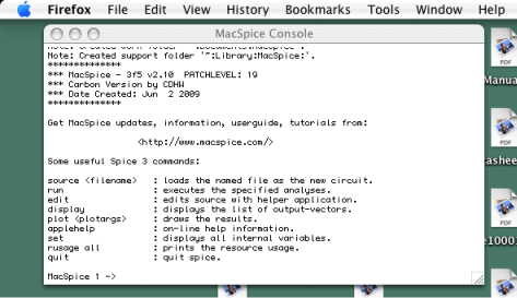 I've been using MacSpice for Mac OS X. The tool remains text based, but with some menu wrappers for a few functions.
Revisiting Pokey's Fan Motor Circuit: You may recall the crappy, last minute, motor driver circuit I threw together for Pokey, my firefighting robot. I want to use modeling to analyze the existing circuit and to help me come up with a better design.
But first, let's talk about SPICE. The MacSpice website has good documentation:
I found the following websites helpful, too:
- SPICE Tutorial
- Quickstart Tutorial for SPICE 3
- SPICE Simulation Fundamentals
- B2 Spice AD FAQ
- DC Motor Modeling
 Let's start with a much simpler circuit; we'll ditch both transistors and represent the motor as a simple resistor, tying it directly to 9V and GND. We'll keep the capacitor and 9V battery. Here's the circuit with the nodes labeled to make it easier to enter into a SPICE file.
| Note that the GND node must ALWAYS be node 0 or you will get errors like "Warning: singular matrix", "Warning: source stepping failed", "Warning: gmin stepping failed", "No convergence in DC analysis", and "failed to converge". I spent about 2 hours trying to find out that I simply needed to number the ground node zero!! |
Let's start with the voltage supply. A simple DC supply is described by Vname n+ n- value where n+ is the positive node, n- the negative node and value is the DC volts value.
Next, there's the "motor" resistor described by Rname n+ n- value where value is the resistance, let's say 1Ω.
The capacitor is described by Cname n+ n- value as you might expect. (It has another option, the initial voltage, but we'll ignore that for now)
Note that SPICE can represent kilo, mega, milli, nano, pico, micro, etc. with a code (K, Meg, M, N, P, U, etc., respectively) so our 100µF cap value is represented by 100U. Here's the SPICE file. Comments are preceded by an asterisk (*)
| Example SPICE FILE * Voltage supply is across nodes 1 and 0 V1 1 0 9.0 * Resistor in parallel on nodes 1 and 0, 1 ohm R1 1 0 1 * Capacitor in parallel on nodes 1 and 0, 100uF C1 1 0 100U |
The first line of a SPICE file is always the title. Don't forget that or the component you put on the first line will be missing when SPICE analyzes the circuit!
So, create the file, example1.cir, and put the above text in it. You can load it into MacSpice (or whatever SPICE program you use) and analyze it. Here's what I got:
| MacSpice 8 -> source # User selected - example1.cir Circuit: Example SPICE FILE MacSpice 9 -> op MacSpice 10 -> print v(1) v(1) = 9.000000e+00 MacSpice 11 -> print i(v1) i(v1) = -9.00000e+00 MacSpice 12 -> |
You may wonder what the op, and print statements do. The op command tells SPICE to analyze the operating point (steady state). The first print statement above displays the voltage at node 1, v(1), which is 9V as we would expect. The second displays the current supplied by the v1 supply, i(v1).
That's good enough for now. In the next article I'll add more complexity to the model more complicated and do more with the analysis of the circuit.
[Part 1 2 3 4 5] >>
nice post
ReplyDelete