Tuesday, September 16, 2008

Squeaky: Chassis Done

Squeaky < prev | next >

Time is running out for robotics. My last class of the year started last night and the spectre of impending homework, reading, projects... Meanwhile my shelves are now packed with hundreds of recently acquired, filthy records pining away for a good record cleaning machi--err, record cleaning robot. Squeaky. As you know I'm kind of winging it on this one.

Squeaky is going to use a motor/sprocket/tooth-belt assembly from a bread machine with an idler wheel attached, so the entire assembly needs to pivot. Idler wheel pressure will be controlled by a spring. The previous incarnation led to a rather floppy assembly due to play in the single bronze bushing.

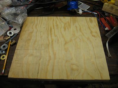
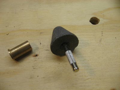
The new version uses a 3/8" threaded rod as the axle, with two bronze bushings to control wobble. I started with a 3/4" plywood base (leftmost picture below) of 13"x15" based on some mockup measurements. The base houses the lower bushing. A hole with chamfer (middle picture) makes it easier to hammer the bushing into place. A wood tower houses the topmost bushing and the threaded rod goes through both (rightmost picture below).


Lock nuts will cinch against the thrust surfaces of the bushings and hold the threaded rod and bushings in place and allow for end play adjustment.

With the pivoting rod in place, all that's needed is the serrated lock nuts to clamp on either side of the motor platform and now the pivoting drive assembly is held securely with nearly no wobble.

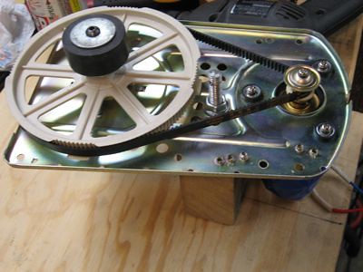
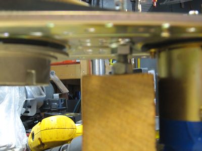
In the picture (above right) despite the dreadful fuzziness, you can make out the lock nut on the bottom and the serrated lock nut above it, holding up the bottom of the motor assembly. Another neat feature of this arrangement is that the height of the motor can be adjusted precisely.

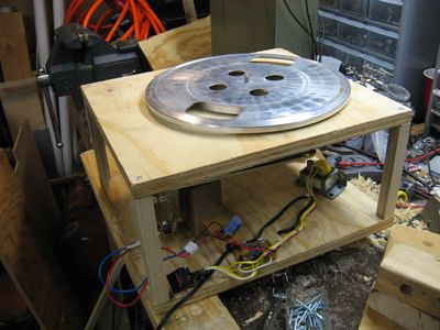
The upper platform is 3/4" plywood, same dimensions, into which I installed the turntable spindle assembly, and cut a hole through which the idler wheel will protrude. It's not pretty but it works and it won't be visible during normal operation.

The top platform is supported by four 1" square dowels screwed into place form top and bottom (below left). Also not pretty. But, I do plan to dress this thing up once I get the details worked out. I had to make a few minor modifications but in the end, it seems to work, there's room for the vacuum, for the fluid reservoir, etc. The mechanism seems a lot tighter and more precise than my earlier mock up.


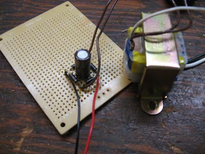
Regarding the electronics... I accidentally blew up the transformer that came with the bread maker but I was able to salvage an entire power supply including fuse, switch, transformer out of the junk linear tracking turntable I got for free and it all works beautifully with my homebrew bridge rectifier (above right).


Squeaky < prev | next >

Saturday, September 13, 2008

Esquire E-Ink Magazine Cover

I'm sure you've heard about the Esquire E-Ink cover? Everyone's blogging about it so I guess I have to, too. Picked one up today.The thing doesn 't do enough to impress my wife :) but I think it is pretty neat. Better, it appears to be hackable according to Make. It's got a PIC processor, 5-pin programming header, and two e-ink flexible screens that apparently can be switched. I notice the development kits over at e-ink cost $1500-3000 so... no plans to create my own custom robot displays until I win the lottery... I wonder if you can do anything with just the processor...

Saturday, September 6, 2008

Squeaky: Power Supply and Motor Demo

Squeaky: < prev | next >

Squeaky's 24V motor power supply is operational. Eureka!

I blew up the bridge rectifier that came with the bread maker so I used four 1N1004 rectifier diodes that were in the parts bin to make a diode bridge with a 1000µF cap in the middle to smooth out ripple and provide a little reserve current. My very first AC-DC power supply!

I reused the bread maker transformer which is a 24VAC with center tap. I noticed Radio Shack had a number of these for sale. I am hoping to figure out a way to do a dual output supply but for now I have the ~32VDC that I need.

The only downside is that the motor spins a bit slow, so with the additional reduction of the small rubber drive puck, the platter is spinning quite slow. That may need correcting.

Squeaky: < prev | next >

Thursday, September 4, 2008

Squeaky: Why Vinyl?

Squeaky: < prev | next >

You may be wondering why a guy that's into robotics would want anything to do with records. They're so last millenium! I've always enjoyed the experience of playing records and I recently discovered that LPs can rival CD sound quality. Provided the records are well cleaned and played on a good turntable.

As we all know, the word robot comes from the Czech robota, figuratively meaning drudgery, or hard work. Nothing could better describe the process of cleaning LPs. It really sucks. And that's where Squeaky comes in.

In case you still don't believe LPs can sound good, here's an audio clip comparing the CD and LP versions of the same recording of Mozart's Oboe Concerto. Have a listen.

Squeaky: < prev | next >

Squeaky: Drive Mockup

Squeaky: < prev | next >

Squeaky the Record Cleaning Machine is coming along nicely. Last night I spent a few minutes mocking up the drive mechanism (left) after a short trip to the hardware store.

If you look closely, there is a nut between the white plastic driven sprocket and the motor sprocket, slightly off-center. That is the pivot point for the drive chassis. With a spring forcing the idler wheel against the platter as shown, precision mounting isn't necessary, the amount of force can be made adjustable, and the device is wear tolerant.

The pivot itself is super simple as the series of pictures below demonstrate. A bronze bushing is press fit into a block of wood (below left) and a 3/8"x2" bolt slides through the bronze bushing acting as the axle.

The non-threaded portion of the bolt rides in the bushing. The two serrated lock nuts (below center) clamp onto the drive chassis which required one of the existing holes to be enlarged. Note the washer pictured below. It's probably unnecessary and will just wear out; it would be better for the nut to ride against the bushing directly.


The block was a bit thicker than the bushing so for the mock up, a hole in the block on the bottom side (above right) allows the bolt to slide up against the bottom of the bushing and also allows the entire assembly to be mounted to a flat surface without interference.

I realize none of this is very pretty. It is a mock up after all. Now that I have a sense of how it goes together, I'll revise the mounting blocks for the platter and drive chassis, making them one block, and more compact. If you can't tell I am pretty much making this up as I go, rather than trying to draw / draft it all out ahead of time.

Meanwhile I'm in the process of procuring some inkjet printers that will donate their stepper motors for controlling the motion of the cleaning, scrubbing, vacuuming arm(s). My only concern with using stepper motors is the expense of a controller. Other alternative: a cheap servo, if it is strong enough to do the work.

Squeaky: < prev | next >