<< [Part
1 2 3 4 5]
To continue with the SPICE experimentation, let's take a look at doing a better job of simulating a motor while using the SPICE subcircuit (
.SUBCKT) feature.
Here's a fantastic article from eCircuit Center on modeling not only the electronic but the mechanical properties of a DC motor in SPICE. I'll let you read the article yourself to get all the nuances.
Subcircuits OverviewMeanwhile, I'd like to take the motor definition and turn it into a subcircuit in SPICE. Subcircuits provide a way to encapsulate a lot of electronics detail, like that of an
op amp, logic chips, or other integrated circuits, while presenting a simple interface to the main model in the form of external nodes, aka input/output pins.
Our motor subcircuit will have two external nodes: A, and B. These represent the two terminals you'd see on this on any DC brush motor. This subcircuit will plug into our earlier circuit in place of the resistor R
M that we were using to simulate a motor.
Here's what the motor simulation circuit looks like. For a full explanation of the circuit see the
article referenced above. This diagram was drafted in LTspice, a Windows-based implementaiton of SPICE that makes it extremely easy to draft and simulate circuits. I sort of spontaneously decided to give LTspice a try.
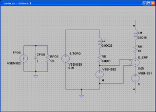
A side note: if you work this out yourself, I ran into some glitches trying to build a current controlled voltage source in LTspice, the E_EMF above. If you use the drawing above, you get a different motor simulation than if you use the file provided on the DC motor simulation website.
Before we go further, I want to talk a little about LTspice.
Quick LTspice OverviewLinear Technology's
LTspice is a Windows program that combines circuit CAD and SPICE simulation. I've been hearing about it over on
Electro-Tech-Online forums and with the recent
series on SPICE using MacSpice I figured why not give this little gem a try. Having just acquired a $5 1.5GHz Pentium 4 tower with Windows XP at a nearby yard sale, there's no time like the present.
Not to make this into an LTspice user guide or extensive tutorial, here is a quick overview of the software. In short, the process for using the program is:
- Add components,
- Define component models,
- Wire components, and
- Set up and run the simulation.
On the right side of the toolbar is the set of icons for adding components to the schematic.
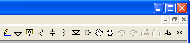
Resistors, capacitors, inductors, ground, and diodes each have their own symbol.
Transistors and voltage supplies are added via the add component button which looks like an AND gate. From a dialog box, you select the type of component such as, LED, MOSFET, JFET, Comparator, Voltage Regulator, and more, even custom components (more on this later). In our case above, an NPN transistor, and voltage (supply).
Once you have components in place, you specify details about them, like passive component values, supply voltages, supply types (
PULSE, SINE, etc), transistor models (e.g., 2N3055 or 2N2222), and so forth.
Wire the components with the pencil icon which features a handy vertical & horizontal alignment rules. You can easily move or drag components or entire sections of the circuit, rotate them, mirror them. It's really simple to quickly create your circuit diagram and lay it out just how you want.
Once you have your circuit defined you can run a simulation. In this case I chose to run an operating point simulation. Just select
Edit simulation command from the
Simulate menu. Select the
DC op pnt tab and click Ok. Place the
.OP directive onto the sheet. A similar procedure would be used for transient, AC or DC analysis.

Now select
Run from the
Simulate menu or click the run icon in the toolbar and you get very readable outputs (unlike the raw SPICE or MacSpice output). Now that we've briefly reviewed LTspice, let's get back to improving the motor simulation.
SubircuitsTo encapsulate all the motor simulation circuitry above into a subcircuit, the circuit description is wrapped in SUBCKT / ENDS cards. The SUBCKT line specifies the name of the subcircuit and the number of externally accessible nodes ala:
.SUBCKT SUBNAM N1 [ N2 N3 ... ]
.ENDSSubcircuits are referenced (called) by the pseudo-element identifier
X followed by whatever name assigned to the instance of the subcircuit:
XYYYYYYY N1 [ N2 N3 ... ] SUBNAMFor our motor, we'll use the following sort of template.
.SUBCKT motor A B
*
* Motor description cards go here
*
.ENDS |
Node A will be the + voltage supply terminal, and B will be the - terminal.
Motor ModelHere's the SPICE deck for the motor from the website above, less the voltage supply and analysis/print directives and with the
.SUBCKT / .ENDS cards added. I also changed the series resistance,
RA, to 16Ω. While I was toying with all this, it seemed that 16Ω resulted in a motor with current requirements compatible with our original circuit, about 490mA, steady-state:
.SUBCKT MOTOR A B
* MOTOR VOLTAGE
RA A 2 16
LA 2 3 0.0015
H_EMF 3 4 VSENSE2 0.05
VSENSE1 4 B DC 0V
*
* MOTOR TORQUE BASED ON INERTIA AND FRICTION
H_TORQ 6 0 VSENSE1 0.05
LJ 6 7 0.00025
RB 7 8 0.0001
VSENSE2 8 0 DC 0V
*
* MOTOR POSITION
FPOS 0 11 VSENSE2 1
CPOS 11 0 1
RPOS 11 0 1MEG
.ENDS
|
As mentioned before, the subcircuit generated by LTspice looks a bit different:
.subckt motor a b
LM a N002 0.0015
LJ N001 N004 0.00025
RM N002 N005 16
RB N004 N006 0.0001
E_EMF N005 N007 N006 0 0.05
VSENSE1 N007 b 0
VSENSE2 N006 0 0
H_TORQ N001 0 VSENSE1 0.05
FPOS 0 N003 VSENSE2 1
CPOS N003 0 1
RPOS N003 0 1m
.ends motor |
Including FilesSPICE also lets you include entire files via the .
INCLUDE card. I used this when simulating the motor in MacSpice.
.INCLUDE filename
So let's put the motor subcircuit in a separate file,
motor.cir, and we can include it into our earlier circuit description.
Custom Components in LTspice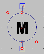
Whereas in MacSpice one has to manually set up files with subcircuits to be included, LTspice front ends these SPICE features by enabling the user to create new components. First, you draft a new symbol, in this case, I drew a typical motor symbol (right), a circle with an M in it, and two pins (ports) shown as squares.
Next you set up a schematic in the same directory and with the same base name as the symbol (e.g.,
motor.asy and
motor.asc). You associate the pins/ports on the drawing with those in the schematic and now you can just plug in this component by adding it out of your directory just like you'd add any other LTspice component. This is a pretty clever approach that gives LTspice a lot of flexibility and power.
Behind the scenes, LTspice is using subckt cards to implement this hierarchy. It puts the subcircuit description inline in your circuit diagram when you load a component. You can see how this is implemented by selecting
View>SPICE Netlist.
Hooking up the MotorIn MacSpice you can include the subcircuit file, so after adding the appropriate file include card, we replace R
M, connected to nodes 1 and 3, with a call to the motor subcircuit (
XMOTOR 1 3 MOTOR). So here's what we end up with:
Motor driver
*
* Sources
*
V9 1 0 9.0
V5 2 0 5.0
*
* Simulate motor as resistor
*
.INCLUDE Macintosh\ HD:Users:mes:Desktop:motor.cir
*RM 1 3 18
XMOTOR 1 3 MOTOR
* Measure motor current
VM 3 4 0
... |
The complete MacSpice circuit file is here:
ex5.cirMeanwhile, using LTspice, I created the motor driver circuit, replacing R
M with the motor custom component and then added a few extras. To simulate the 5V logic signal from the AVR microcontroller, I installed a voltage controlled switch, S1, which is repeatedly turned on and off by a 5V PULSE voltage supply.
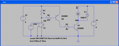
When I simulated the circuit at first, as expected, I was seeing massive voltage spikes across Q1 because of the motor's inductance. The cure for this is to place a schottky diode across the motor itself, D1 above.
Note that when using a MOSFET driver instead of a BJT, a diode is present within the transistor package. However, I've seen advice to use an external diode just in case the current or voltage is too high for the internal diode to handle.
Finally, I added a pull up resistor, R1, to ensure that the transistor is off when the AVR MCU's output pin is in a high impedance state (during reboot, MCU off, etc.). The only way to turn on the motor is if MCU sets the pin low to sink current.
Simulation ResultsIn LTspice, to do operating point analysis, I bypassed the S1 switch and hardwired the base resistor to ground. Here are the results. The interesting results are in blue.
V(m2): 0.111133 voltage
V(n005): 0.496462 voltage
V(n004): 4.95934 voltage
V(m1): 9 voltage
V(n002): 4.04701 voltage
V(n001): 5 voltage
V(n003): 0 voltage
Ic(Q3): -0.0495875 device_current
Ib(Q3): -0.00861067 device_current
Ie(Q3): 0.0581982 device_current
Ic(Q1): 0.555551 device_current
Ib(Q1): 0.0495875 device_current
Ie(Q1): -0.605139 device_current
I(D1): -3.17e-005 device_current
I(R1): 0.005 device_current
I(R3): 0.00861067 device_current
I(R2): -0.0495875 device_current
I(S1): 0 device_current
I(Vsw): 0 device_current
I(V2): -0.0631982 device_current
I(V1): -0.555551 device_current
Ix(1:A): 0.555519 subckt_current
Ix(1:B): -0.555519 subckt_current |
Note that LTspice displays all currents without having to insert 0v supplies -- it does this behind the scenes. A nice feature!
Also, it usually displays voltages by referencing the device name, rather than the associated node names, making it a bit easier to understand the results.
Finally it displays the values as decimals rather than scientific notation so there's no mental calculations (e.g.,
let's see 0.1E-2 is, uhh... 1mA...)
So we're seeing about 556mA through the motor. When I used the subcircuit file given by the DC Motor simulation website, apparently the back emf behaves a bit differently than what I drew up in LTspice because current is quite a bit lower, about 217mA. So, time permitting I'll play around with different values of the components in the motor simulation. At some point it would be handy to be able to model any motor based on datasheet specs. But that's best saved for a whole 'nother article.
Next, I performed transient analysis in LTspice. The software makes it easy to graph the results; run the transient analysis, then click on areas of the circuit with your virtual 'probe' to read voltage/current.
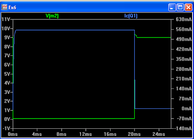
MacSpice plots looked the same, in case you were wondering. Notice the voltage clamping effect of the schottky diode. The motor is still generating small voltage spikes at turn on and shut off, but they are orders of magnitude smaller than before. One concern I had was that motor current would spike (stall current) when turning on. Not so.
Instead, both spice simulations seem to show a gradual ramp-up of current. Is this because the Q1 transistor is going out of saturation when the motor first fires up, because I
C is so high initially? (I
B less than I
C ÷ ß). Something else I can investigate later.
Motor Driver Next StepsSo I'm pretty happy with the simulations at this point. My next step is to gather real data on the motor, particularly its steady state current requirement with the fan attached. I think using the complex motor subcircuit isn't necessary to model a motor that simply turns on for a few seconds to blow out a candle.
So modeling the motor as a simple resistor would be good enough to let me modify the circuit above to drive the motor. Or, better yet, find a different driver transistor since the TIP3055 (2N3055) is total overkill and model it, instead. Whenever I get around to driving a 15A(!) motor I might put one of these to use again. :)
Another thought is to use a MOSFET transistor but an N-channel would need some driver hardware to get the gate voltage above the drain voltage. Another idea is to use a dedicated motor driver IC but I kind of want to stay old school with discrete components.
Of course, I can also use a different motor. It'd be simpler to use the robot's existing supply voltage and a 5-6V motor than having to tack on a 9V battery. It's more of a challenge to design around all the constraints of using parts you have on hand.
That's ItSo, that's it for the SPICE series. Hope it's been helpful and/or interesting. Thanks for reading!
This isn't the last time I use or post about SPICE. I want to improve the IR LED flame detection circuit soon. SPICE will, I think, provide a good way to model what is happening and work on improving the amplifier part of this circuit.
Also, since I didn't get around to talking about converting between Eagle circuit drawings and SPICE decks, I'll post about that in a separate article at some point.
Special thanks to the electronics gurus at Electro-Tech-Online for some input and advice on BJT saturation.<< [Part
1 2 3 4 5]
 My first prototype of the mini function generator is now officially done. It's a tight fit inside that Hammond 1593 project box from All Electronics, but it works.
 Clearance for the switch and the BNC connectors is pretty tight and I had to saw out some unused parts of the PCB to get it to fit. The PCB is mounted with plastic standoffs from Radio Shack. The plastic standoffs are glued to the case with Sure Hold Plastic Surgery. Note that this isn't my idea, but rather came from this Sparkfun Tutorial.
 I swapped out the LM258N Op Amp for an LM1458CN which apparently has a faster slew rate as the trace is substantially cleaner than the one generated by the 258. No spikes, no ringing, etc.


