
Here's my Raspberry Pi telepresence rover robot. You can make one yourself and explore your house from your web browser, iPad or iPhone. Just read the tutorial
Overview
The setup is simple, using readily available hardware and software for motor control and streaming video. The rover consists of a Raspberry Pi in an enclosure sitting on top of a tracked chassis. Low voltage motor controllers are driven by the RPi GPIO pins controlled by REST services called from a control webpage via JQuery. |
| Meet Dragon. Streaming video top. Controls, bottom. |
Let's start building the Raspberry Pi robot from the bottom and work our way up.
You'll Need
- 1x Raspberry Pi Model B
- 1x MicroSD card with Raspberry Pi Wheezy
- webiopi software for Raspberry Pi
- mjpg-streamer software for Raspberry Pi
- EDIMAX USB wifi
- 1x Pololu 30T track kit
- 1x Pololu idler wheels
- 2x 150:1 Pololu gear motors
- 1x Pololu Step-Down Voltage Regulator D15V35F5S3
- 1x Pololu motor brackets
- 1x Sparkfun 3.3V FTDI breakout board
- 1x Microsoft LifeCam HD6000 (or equivalent, low power USB Webcam)
- 16x #10 nuts
- 4x #10 x 1" screws
- 2x #10 x 3/4" screws
- 1x 3/4"x1/2" aluminum 1/16" thick L-bracket cut into 2x 4" lengths
- 1x 1/2" aluminum 1/8" bar stock, cut to 5" length
- Hookup wire, various colors
- 30x Multicomp 2226TG (includes extras just in case)
- 1x Multicomp 2226A-02
- 2x Multicomp 2226A-04
- 3x Multicomp 2226A-06
- Cyntech Raspberry Pi enclosure
- Polycarbonate (Lexan) cut to 4" x 4" square
- 6C NiMH battery (or you can use 2S LiPo)
- Deans/Tamiya/XT60/Traxxas/etc. battery connectors
Chassis, motors, and motor control
The chassis is built on the Pololu 30T track kit. It comes with tracks, a pair of idler wheels and a pair of drive wheels. I added another pair of Pololu idler wheels and mounted the idlers on short sections of aluminum L stock.
The drive wheels are mounted onto 150:1 Pololu gear motors which in turn are mounted to the top of the L stock with Pololu motor mount brackets. Solder 6" wires on the motors and attach female crimp connectors (Newark: Multicomp 2226TG) on the ends.

I assembled each side independently, then cut a Lexan (polycarbonate) base. How do you cut polycarbonate? Carve a straight groove with a wood carving tool (like one of these) and a straightedge, then bend it in a vise for a clean break.
Mount each aluminum L channel to the Lexan base with 1" long #10 screws and nuts. Extra nuts raise the base above the motors.
 |
| Note the wires: female crimp ends with heat shrink |

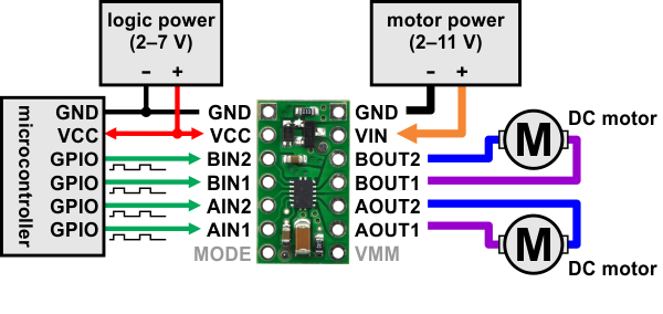
A Pololu DRV8835 motor controller handles the tricky task of driving the motors. Install 0.1" pin headers on the board. Using Pololu's diagram, insert your motor wire crimp connectors into a 4-way housing (Newark: Multicomp 2226A-04) and plug the assembly onto the motor controller board.
 |
| Image from Pololu.com |
Battery, Power Supply
The robot runs off RC Car batteries like a Reedy Wolfpack 3600mAH NiMH battery. Why antiquated NiMH battery technology? Because I happen to have an automatic NiMH charger that I plan to hack into a docking station. Drive the robot up to it and charging begins.A Pololu Step-Down Voltage Regulator D15V35F5S3 converts the battery power to a usable 5V for the Raspberry Pi and the motor controller. This is the same switching voltage regulator powering the electronics on Data Bus, my 20 mph autonomous RC rover. Install two 4" lengths of wire to the regulator to connect to the battery. On the other end, install whatever connector your battery pack requires (Tamiya, Deans, XT60, Traxxas, etc.)
Cut off a few inches of a micro-B USB cable, strip the wires, and connect the power wires to your regulator board output. This cable plugs into and powers the Raspberry Pi.
For powering the motor controller, cut a 3-5" length of black and red wire respectively, add female crimp connectors, and insert into a 2-way female housing (Newark: Multicomp 2226A-02). Plug this assembly into the VCC/GND pins on your motor controller board.
 |
| Battery mount is aluminum bar stock mounted lengthwise |
 Wiring Raspberry Pi IO
You'll need nine 4-6" wires with female crimp connectors on both ends of each wire. Six of the wires are for the motor controller. One is for 3.3V motor power (the motors don't draw much current), the other five are for control. The remaining three are for serial communications.
Motor control: Following the Pololu diagram above, and Raspberry Pi pinout, insert 3.3V and control wires into a 6-way socket (Newark: Multicomp 2226A-06) and plug into the Raspberry Pi. At the other end, insert the wires into another 6-way socket. Connect Raspberry Pi GPIO pins to motor controller pins as follows:
- GPIO11 to MODE,
- GPIO9 to AIN1/APhase,
- GPIO10 to AIN2/AEnable,
- GPIO21 to BIN1/BPhase,
- GPIO22 to BIN2/BEnable.
If you have a Revision 2, you'll need to use GPIO27 and tweak the software accordingly.
Serial comunications is really handy. I use a Sparkfun 3.3V FTDI breakout board with 4 pins: 3.3V, TXD, RXD, GND. Insert one end of the remaining three wires into a 6-way female housing, the other end into a 4-way female housing. You'll connect the wires from RPi to FTDI Breakout as follows: GPIO 14 to RXD, GPIO 15 to TXD and the nearest RPi GND pin to FTDI GND.
Raspberry Pi Setup
Now that everything's wired, you can set up the Raspberry Pi. You can connect a monitor and keyboard or you can set it up using your FTDI connector and a terminal emulator on your PC.I used a standard Raspbian Wheezy distro. I installed an EDIMAX USB wifi dongle for wireless connectivity and I configured it with a static IP address. You'll need to install webiopi and mjpg-streamer.
Controlling IO
Now that everything's wired up, and the Pi is set up, it's time for software to take control. I've made the entire source available (see below) so you can just download it and put it in place on your Raspberry Pi.The DRV8835 motor controller uses a mode pin and four PWM pins. Details on how to use the board are found on the product page. I'm using webiopi to control PWM on the four motor GPIO pins to move the robot. Here's how it works.
The web page includes rover.js which I wrote. It contains jQuery functions for controlling direction: fwd(), stop(), spinLeft(), spinRight() and rev(). These functions are called when control buttons on the web page are clicked (more on that momentarily).
In turn, these functions call the appropriate webiopi functions available by including webiopi.js. Webiopi jQuery functions call REST services to set PWM parameters on the GPIO pins. Here's an example of how I'm calling webiopi from within the direction functions.
Web Interface Buttons
The web interface has an HTML table with cells forming buttons for each of the available directions (forward, reverse, stop, spin left, spin right). We use jQuery to detect when those buttons are clicked and call our jQuery direction functions.But our table cells aren't buttons. Normally, clicking a table cell doesn't make it blink. Also, double-clicking a cell will select the contained text. We can make the cells act like buttons with a little CSS and jQuery.
The following CSS disables text-select in popular web browsers.
html {
-webkit-touch-callout: none;
-webkit-user-select: none;
-khtml-user-select: none;
-moz-user-select: none;
-ms-user-select: none;
-o-user-select: none;
user-select: none;
}
The following CSS makes the entire text cell change color from grey when you click on it. Every cell is given a class of "button".
| td.button { |
| width: 80px; |
| height: 80px; |
| font-family: Arial; |
| font-size: 20pt; |
| font-weight: bold; |
| color: black; |
| background-color: grey; |
| } |
| td.button:active { |
| background-color: red; |
| } |
Now, bind mouse events to the cells and call our jQuery direction functions when those events occur.
On desktop/laptop web browsers, one uses the mousedown and mouseup events to detect mouse clicks on the buttons. Browsers on the iPad and iPhone first fire touchstart and touchend events when you press and release a button and then they fire mousedown and mouseup. If you don't disable the mousedown event, the Rover will move, stop, then move briefly again as if you clicked the button twice.
Bind mousedown/mouseup, touchstart/touchend like this, to call our direction functions and to disable mousedown for iDevices:
$("#F").bind("mousedown", fwd);
$("#F").bind("mouseup", stop);
$("#F").bind("touchstart", function() {
fwd();
$(this).unbind("mousedown");
});
$("#F").bind("touchend", function() {
stop();
$(this).unbind("mousedown");
});
Examples of our direction functions, fwd(), rev(), stop(), spinLeft() and spinRight() can be found above.
$("#F").bind("touchstart", function() {
fwd();
$(this).unbind("mousedown");
});
$("#F").bind("touchend", function() {
stop();
$(this).unbind("mousedown");
});
Examples of our direction functions, fwd(), rev(), stop(), spinLeft() and spinRight() can be found above.
Streaming Video
Streaming video originates from a Microsoft LifeCam HD-6000 with it's annoying, unnecessary autofocus disabled. The web streaming is made possible with MJPG-streamer. It runs its own web server on the RPi.My control page simply includes an IMG tag: <img id="streamimage" src="http://192.168.0.4:8080/?action=stream" /> to display the streaming image.
 |
| Screen capture from today's cat observation mission |
The camera is mounted with double-sided tape to a section of aluminum bar stock I bent into an L shape. That in turn is mounted to the RPi enclosure.
Thank you so much for making this post so clear and explanatory. I only have one question that I'm a bit confused about: how does one go about connecting the motor driver to the GPIO? Sorry, I'm don't know very much and have never seen either in person (the driver or Raspberry Pi GPIO.)
ReplyDeleteThanks for the question! I added more details turning this article into more of a tutorial than show-n-tell. It includes connectivity between RPi and DRV8835 motor controller.
DeleteMagnificent! We are starting a Robotics club and this should wet everyone's appetite.
ReplyDeleteNice project.
ReplyDeleteIt beats the usual media centre use for a Pi, and combines some nice features.
Well done
Mark
Hi, very nice project. I am trying to get the same webcam to stream with mjpg-streamer. I'm having trouble. Is there any way you could help me with this? My skype name is jb.baker1
ReplyDeletethanks!
Thanks! What seems to be the problem? Click on the "contact me" link at the top of the blog if you want to email me.
Deletehai superb your project
ReplyDeletewhich language used to control motor from website?
how to configure website+raspberry pi wireless?
Hi, thanks for the details, but I have 1 question, where is GPIO 21 that is connected to BIN1/BPhase on Raspberry Pi? According to the link you gave, I don't see GPIO 21, can you help me with that?
ReplyDeleteThank you!
For Revision 1, it's the in next to GPIO22. On Revision 2 you'll have to use GPIO27, apparently, which means tweaking hte source a bit. (http://www.megaleecher.net/Raspberry_Pi_GPIO_Pinout_Helper). I'll update the article.
DeleteOh, thank you. What do you mean by tweaking the source? An example maybe?
DeleteThe rover.js makes references to GPIO 21, so, for example, webiopi().pulseRatio(21, 0); should be changed to webiopi().pulseRatio(27, 0);
DeleteMichael,
ReplyDeleteThanks for your ideas and code on this rover. I am trying to replicate a similar design to what you have and i am running into an odd issue. For whatever reason my rover does not accept any input when the command given to it is via "webiopi().digitalWrite(9, 0);" in HTML or in Javascript.
I tested the outputs and know they are working via the io.html (WebIOpi's default test app) also making a button via the:
"button = webiopi().createGPIOButton(7, "LED");"
command in HTML works fine too.
I am wondering if there is another part of configuration that i omitted someplace? For example are you using a python script to drive any of this html/js code? Any ideas appreciated!
This comment has been removed by the author.
ReplyDeletehow can i make the code of raspi from the beginning ??
ReplyDelete