Showing posts with label sketchbook. Show all posts

Friday, October 23, 2009

Edward Isaac Bot: Sketchbook 5


The weird third eye thing on this alternate sketch of EIB is supposed to be a Polaroid sonar transducer. But much has changed in the last 15 years in the way of robotic rangefinders.

Pokey uses Sharp GPD12 infrared rangers (right) which provide surprisingly accurate results. They determine distance based on the angle of reflection. They're cheap, only $12 each, and they're small, maybe 1.5" x 1/2".

There is a whole family of IR rangefinders, each with a unique (but somewhat limited) distance range. The GPD12's 4"-30" range seemed ideal for measuring distances within the firefighting maze in which Pokey competed.

Modern sonar systems are significantly smaller and also inexpensive, about $30 for something like the Devantech SRF04 Ranger (right). The device is about 2" x 3/4" and includes the driver circuitry on the back of the board.

This particular model uses a separate transducer and receiver. However, you can also get single transducer/receiver models. This device can measure distances from 3cm to 3m!

Of course in the 1990's, tiny cameras with any kind of image processing fell into the realm of impossible or unaffordable.

The CMUcam2+ (left) is able to do high contrast color tracking, all in a 2.25" square package. How times have changed!

There are a number of sources for this gear. I got a sonar ranger from Radio Shack when they were having a sale. I got my Sharp rangers from Acroname (the source of the pictures and info above; no advertising affiliation with the company, I just like 'em).

Friday, August 14, 2009

Edward Isaac Bot: Sketchbook 4

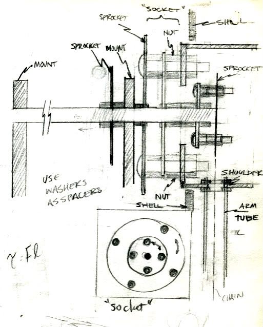
Here's another artifact from the old EIB sketchbook. I was trying to figure out how I was going to build the mechanicals for the shoulder, arm, and elbow.

The concept is a drive sprocket for the elbow that shares the same rotational axis as the shoulder and its drive sprocket. The elbow drive sprocket in turn drives a sprocket in the elbow with the chain running through two arm parallel arm tubes. The sketch needs a little work. The shoulder's axle would have to ride on bearings, while containing bearings that support the inner elbow axle. A sprocket would be attached to each axle.

Why actuate the elbow this way rather than having a motor attached to the arm itself? So all the big arm motors could sit inside the chassis instead of adding weight and bulk to the arms. And center of gravity can be kept low. Is it workable, practical? I have no idea.
Never did try to make this. The other concept in play here was that the shoulder would be somewhat easy to remove, by undoing a few lug nuts similar to removing a tire. Speaking of automotive analogies...

This sketch got me to thinking about the many times in the intervening years that I've taken apart my Jeep's front hub and full floating axle assembly (see pic below). Maybe axle designs will be of interest to the robot designer...

The way a 4x4 floating front axle works is this. The tire is bolted to the hub. The hub (67) spins on the spindle (62) by way of inner and outer wheel bearings (65, 66). These bearings bear the weight of the vehicle, which is transferred through the suspension to the axle housing, to which the spindle is attached.

Meanwhile, the spindle is just a tube and through it runs the axle shaft (56). A bearing inside the spindle (61) supports the axle shaft. The end of the axle shaft has splines cut into it. The inner surface of the hub has splines, too. A drive flange is a puck of steel with a hole in the middle. The hole has splines and slides onto the axle shaft splines. The outer edge of the flange has splines too and those engage the hub splines. But most 4x4s use manual locking "hubs" (73-76) instead of a drive flange so that the axle shaft can be engaged with the hub & rotor assembly (67) when in 4wd and disengaged when in 2wd.

Kind of an interesting concept that allows the axle tube, bearings, spindle to bear the weight of the vehicle, so that the only thing the axle shaft does is transfer torque. By contrast, in a semi-floating axle like you'd find on the rear of 1/2 ton trucks with "live" axles, the wheel bearings are pressed onto the axle shaft and ride on a race that is mounted in the axle tube.

The axle shaft has a mounting flange to which the wheel is bolted. In other words, the weight is borne by both the axle tube and the axle shaft itself. This type of axle generally is able to carry less weight than a full floating axle of similar size because the axle takes on double duty.

So, that's 4x4 axles in a nutshell...

Saturday, July 18, 2009

Edward Isaac Bot: Sketchbook 3

Here's some sketches on motor encoders. The basic idea is that, back in the day when MCUs weren't affordable or readily available (the Motorola 68HC11 was popular, I recall), one had to plan for a pretty high chip count.

In this case, some type of counter that would track the number of slots in a disc that whizzed by an IR LED/Phototransistor pair. Remember I was still in college, with limited tools, etc.

So building any kind of precise disc with slots in it was not going to happen (since I didn't know any MechE's that could get me into their fancy machine shops).


But there are other ways to build encoders. You can print up an encoder wheel with a laserjet/inkjet printer and use an IR pair to read reflected light. Or you can print a transparency hoping that the printed spots are dark enough to block light. Or you can use one of these drain strainers or some other piece of hardware that has precisely predrilled holes.

Of course now, too, you can use an MCU to count pulses, and you can by tiny SMD-based IR circuits like those I used on Pokey. And what about broken inkjet printers? The two I've disassembled have excellent transparent encoder discs and IR sensors. (Not to mention a slew of motors, gears, rubber pieces, etc.)

Saturday, July 11, 2009

Edward Isaac Bot: Sketchbook 2

Here's more silliness from the dusty Edward Isaac Bot sketchbook archives. This is a sort of block diagram for the robot. Various audio functions like record/playback and sound generation, as well as basic motor control of head, arms, wheels.

And the obligatory water pistol. Uh... right.

Truth be told, a water pistol feature would come in handy right now to discipline one of our cats who keeps jumping up on the kitchen counter. And in fact I am seriously thinking about refitting Pokey for that sort of guard duty... but that is another story for another blog entry.

So, yeah this was kind of crazy brainstorming. I mean, an air purifier? Really?


Thursday, July 2, 2009

Edward Isaac Bot sketchbook

While I'm working on SPICE modeling and now learning LTspice for the next article in the SPICE series, I thought I'd post up some sketches from "back in the day" when Paul and I were thinking about building a robot. Maybe they're worth a chuckle :) Or maybe there's something interesting in there, I don't know.


One of these days I suppose I will actually try to build this robot...

Wednesday, December 19, 2007

Edward Wheels

Edward Isaac Bot was to be a 2-3' multi-functional, useful, household robot. Good thing Paul and I weren't being ridiculously ambitious and were instead starting with a small, simple project. <- Sarcasm.

Here's some (simple) thoughts about wheel placement & size, and a later sketch of EIB overall shape. Basically, contemplating more forward wheel placement for stability, larger wheel size for more easily driving over small household obstacles. (Since this was written I got a Jeep and took up four-wheeling. Perhaps I can draw from some of my experiences in that realm).

The note about speed assumes a set of motors I'd already purchased, otherwise you could select wheel size & gearing for appropriate maximum speed.

Edward Isaac Bot: Sketchbook 1

Early sketches of Edward Isaac Bot, the concept Paul and I came up with years ago that got me into all this robot stuff.


(You can guess how old this is, given the cassette deck up front and four floppy drive bays in back...)