Welcome new readers! Watch for articles to appear every 1-2 weeks, as if by magic. Podcasts appear... whenever I get around to it. On with the article:
While refitting Pokey the firefighting robot, I revisited the topic of candle flame detection with infrared LEDs, phototransistors, etc.
Originally, I'd used a pair of infrared (IR) light emitting diodes (LEDs) housed in a flashlight reflector housing. It was an inexpensive solution that seemed to have promise. It improved the sensitivity to distant/faint signals and reduced sensitivity to signals outside the regulation 15-20cm flame height.
I wasn't able to perfect the sensor and abandoned it in favor of a custom camera and software solution. Here's a summary of some information I collected along the way. perhaps it will help someone and inspire further investigation and experimentation.
Information originally collected from various Wikipedia articles.
Here's an excellent source of information.
Photodiode: Make use of the fact that LEDs have inherent capacitance. Charge the LED with the MCU interface pin set to output mode high. Then set the MCU interface pin to high impedance CMOS mode, and measure the time it takes for the LED to discharge. The rate of current leakage from the LED is proportional to the ambient light.
Photovoltaic mode: This is the mode I used for Pokey's sensor. Same concept as solar cells which, in fact, are just large photodiodes. Ambient light causes voltage to build up in the device. More voltage means more ambient light. I amplified the voltage with an operational amplifier and read it with an analog to digital converter.
Photoconductive mode: reverse bias the diode, decreasing inherent capacitance. Benefit is faster response times with the tradeoff of increased noise.
Avalanche photodiodes: similar to regular photodiodes but operated with higher reverse bias. Internal gain in the device comes from multiplication by avalanche breakdown.
Phototransistors: basically bipolar junction transistors with clear packaging such that photons reach the base-collector junction. The b-c junction acts as a photodiode whose current is amplified by the transistor's current gain (hfe). No better at detecting low light levels but more input-output gain (responsivity).
Showing posts with label Pokey. Show all posts
Showing posts with label Pokey. Show all posts
Friday, August 20, 2010
Tuesday, July 27, 2010
Firefighting, Robot Expo, Maker Faire

John Maushammer's Asteroids Watch.
Home made SMT at its finest!
My favorite Maker entry by far.
My favorite Maker entry by far.
Illness and family matters took priority the last few days. With both resolved, let me tell you about last Saturday's Robot Expo, mini Maker Faire, and Firefighting competition. The day featured a wide array of great robots, creative gizmos, and cool whatsits.
Firefighting. Perhaps you've been eagerly awaiting resolution of the cliffhanger. Would Pokey succeed in his firefighting duties? When I arrived, the arena was set up, but alas, only two robots were capable of taking to the field in competition. One was fielded by none other than our good pal, Chief Creator of Club Workshop, Stephen Garran. The other was... my very own robot, Pokey!
It was a fight to the finish, a robotic grapple of epic proportion! Metallic minions marching forth to do battle with the Candle, and roll home in victory--or defeat!
...except what actually happened is that Pokey didn't have a fan, and Stephen's robot spun around in circles. (sigh)
The fan motor circuit I had just put together was fatally flawed and so I disabled the fan. But I was able to teleoperate Pokey from my laptop and he consistently searched for and pointed at the candle flame when asked. Not very functional, true, but at least we were able to demo the concept of firefighting to the audience... less the excitement of actually putting out a flame. Ah well.
Robot Expo and Maker Faire. Rather than tell you, let me just show you some highlights.

A low budget cellphone robot


First Lego League arena, left;
David's robotic tank is coming along nicely, right.
David's robotic tank is coming along nicely, right.

RoboRealm

Basil is a voice operated robot with impressive object avoidance capability.


A cellphone controlled Mech faces off against a deadly paper target, left. I forgot whose small robot is pictured above right.

George built a Rubik's cube solver from online plans and software. It solved cubes in just a few minutes.

Extremely beefy rover robot with welded steel tube frame, gargantuan motor controller boards (a dozen TO-220 transistors per channel), wires as big around as my fingers, and dents in the frame that I suspect may have been caused by running down a full grown bull moose.

Kurt's robomagellan with laser rangefinder, GPS, and more.
This beastie was fielded at the Sparkfun Autonomous Vehicle Contest earlier this year.

Underwater ROV using pumps for thrusters
Thursday, July 15, 2010
Firefighting: Another Update

One of the IR pairs for the encoders isn't working. Replacement boards were out of stock but individual chips were available. More are on order overnight--but Sparkfun doesn't do same day shipping. The trick will be to replace an SMT part without a rework station. Tomorrow night.
I'm most likely re-gearing Pokey to be even slower--even though I said I wouldn't. Why? To gain more precise, low-speed control when aiming at a candle.
Outside of robotics, I was picked as a juror yesterday afternoon for a trial which lasted for us until today at 7:00pm. That and some other life stuff going on. I'm beat...
Some code needs writing and the fan motor and board needs mounting. Let's see what I have the willpower and energy to get done with the rest of tonight...
----
* Fixed?? Not so fast hotshot. After posting the above, I discovered that the circuit has a major design flaw. Namely, the MCU cannot turn off the fan. Oops.
Wednesday, July 14, 2010
Firefighting Update

Pokey: Getting Close...
The last few evenings I've been burning the midnight oil. Pokey's camera and vision processor board are mounted to the chassis, encoder discs are installed, and various other details completed.
Only three days left to work on it and there's lots to do.
I had two programs for the main controller. One implemented remote control over bluetooth. The other interfaced with the camera board to point Pokey at a bright light. Fortunately I got this latter pair of programs working again.
If I combine the two I can at least demo Pokey, driving it to a room with a candle, pressing a button, and letting the robot take over from there to find and put out the flame.
Monday, July 12, 2010
Firefighting Announcement and Update
SHARC/FRR Robotics Expo and Mini Maker Faire
Date: Saturday July 17, 2010 Time: 11:00 am - 4:00 pm Location: Club Workshop
Over the last few weeks, the SHARC and FRR roboteers have been working on their robots for the July 17 expo which includes Robot Fire Fighting, Robot Sumo and more.
Pokey, however, is sitting in pieces. {Insert numerous excuses and sob stories here}.

Pokey is a long way from competition
Not much hope of full functionality at this stage but I might be able to get it to detect and extinguish a flame if I just set it down in a room with a candle. The vision / detection system works just fine, albeit at a glacially slow (dare I say "pokey") frame rate. And I was able to code the robot to rotate itself to point to a flame. I'm not giving up entirely. Let's see what I can get done in the next few days. I'll keep you posted.
Saturday, July 3, 2010
Updates
Been really busy lately with work (just got back from a week long business trip) and trying to get my Jeep through emissions. The SHARC gang did take my firefighting arena and started working on it; they're nearly done. I don't know if I will have a chance to go to wherever the arena is to do testing and coding. So I may build another simpler arena again here. Pokey, really, is nowhere close to being ready right now. And there's only two weeks left. Hmm...
Friday, May 7, 2010
Vision-Based Candle Detection
Updated 9/9/2010: Source Code is now available on Google Code.

The Cliffhanger
Having previously interfaced a Game Boy camera to an AVR (Ardweeny / ATmega328P) and successfully capturing an image, the next step in detecting a candle flame was, well, detecting the candle flame.Would the camera be able to capture an image of a distant flame? Would an IR filter work to block out everything but a source of flame?
For that matter, the flame detection software hadn't been tried on an actual Game Boy image yet. And the code hadn't been ported to the memory-constrained AVR yet either.
IR Candle Detection
Using exposed film as an IR filter I got good image results for a distant candle, below, sitting about 170cm from the lens, a typical distance in the real competition. The candle flame is left of center. The center bright spot is the candle's reflection in a glass-covered picture hanging on the wall (but, in the competition, mirrors cannot be placed in the same room as the candle).
The captured image
I added a feature to the client software allowing me to save the captured picture to a file on the PC. Then I processed it into a BMP that my prototype flame detection program could read, and the program it spit out the data for the real candle. It worked!

The detected object
Running Detection Code on the AVR
The flame detection software would have to run on the robot so I redesigned the code to fit into the tiny 2K of RAM on the ATmega328P.Recall that the software essentially performs a flood fill on every pixel brighter than a set threshold. Since it's only purpose is to spit out a set of bounding boxes around detected objects, it really doesn't need to remember the entire image or the flood fills (assignment of pixels to objects) already performed, just the object assignment for the current and prior rows' pixels, from which it can calculate the bounding boxes.
Code Details
The only reason the code needs to remember the prior row is to know if the pixel above the current pixel belongs to an object. Like so:
.. .. 01 01 01 .. .. 02 02 .. 03 03 03
01 01 01 01 01 .. .. 02 02 .. .. 03 ..
It turns out that we never need to look more than one row above, so we only need to keep two rows of object assignments. That's an array of 2 rows, and (in the case of the Game Boy camera) 128 columns.
With the added bonus that we can use a simple XOR operation to toggle back and forth between the two rows: the first time through, row 0 is current, row 1 is previous and the next time through, row 1 is current, row 0 is previous.
Here's the excerpted AVR C code that does the "flood fill".
For what it's worth all the camera and object detection code is just over 4K in size so there's no reason it wouldn't fit in a lower-end AVR.
The Results
Forgetting to take baby steps in program re-factoring, the first attempt was a disaster. The second attempt, however, wasn't. I revised the client code to receive and display the bounding boxes in bright green...
Target Flame Acquired! Distance 185cm

Target distance 100cm
Detection worked well even without the IR filter. With the filter, object detection will probably be more reliable. You'll notice some extraneous objects detected. One is the candle's reflection in a glass holding the remains of an iced latte I made. The other is... a reflection off the computer mouse, I think? Of what, I don't know.
The vision-based detection has come along really nicely. It's pretty darned close to usable right now. Without too much more work, I could hook up Pokey's Orangutan controller to the Ardweeny and it could request and retrieve detected objects and then do something with them.
What's Next?
One of the concepts in iterative development is to focus on solving the hard problems first and leave refinement and easy features for later. I think that makes a lot of sense so I'm going to put the flame detection on the back burner and work on fixing Pokey's navigation problems.But you won't hear about that for awhile. Instead, the next few articles will share the steps involved in proving out how to equip Pokey with a Bluetooth modem.
Updated 9/9/2010: Source Code is now available on Google Code.
Friday, April 23, 2010
GameBoy Camera Prototyping
Updated 9/9/2010: Source Code is now available on Google Code.
Holy TTL, Batman. My cobbled-together code and circuitry works! I just took my first Game Boy Camera picture. Here are all the secrets I know of for interfacing a Game Boy Camera (Mitsubishi M64282FP) to a microcontroller.

First picture!

The actual scene
Summary Version
With Game Boy Camera, Ardweeny running tweaked version of code here, HP 1650A Logic Analyzer to get the timing right, Java Swing desktop application based on code here, and after fixing goofed up wiring and timing it works! Some tweaking of camera configurations and it now takes some nice shots, and the flame detection software does its job with real images, too!
Really Important Tips
- Timing is key when interfacing with the M64282FP
- But, you can also clock the M64282FP as slow as you need to
- Setting the bias (dc offset) voltage to 1.0V is mandatory (the chip outputs 2Vp-p)
- Setting the black level offset correctly is important
- The camera actually spits out 128x128 pixels, but the last 5 rows are junk
- Setting the gain too high can cause odd pixel artifacts (MSB truncation?)
The Long Version
Game Boy Camera
First, I cut wires off of the 9-pin connector, one by one, and spliced them to longer wires and attached each to a small breadboard with 9-pin header so I could plug the camera into my protoboard.
Microcontroller
The Ardweeny from Solarbotics that I recently ordered and assembled lends itself well to rapid prototyping. It's Arduino-compatible running an ATmega328P MCU.
The first step was getting the code put together and getting the timing signals right to activate the Game Boy Camera (Mitsubishi M64282FP image sensor chip aka "Artificial Retina").
I started with code here plus the datasheet. I copied the code into my Arduino IDE and tweaked it as necessary to get it to compile. Then tweaked some more to get the timing right. Along the way, I merged several functions so signal timing was more obvious to me as I read the source.
I ran the code, and... it didn't work. I wasn't getting any response from the image sensor... until I realized I'd crossed a couple of wires on the protoboard. Fixing that, the data came streaming through on the Arduino IDE Serial Monitor. My Arduino code can be found here.
Mitsubishi M64282FP Timing
I've found two versions of the datasheet so far and the timing is a bit ambiguous so let me provide the following hints. If you're in the middle of working with one of these cameras, all this will mean something. Otherwise it won't...
- RESET/XRST has to be low on the rising edge of XCK
- Raise LOAD high as you clear the last bit of each register you send
- START has to be high before rixing XCK
- Send START once
- The camera won't pulse the START pin; the datasheet is confusing about this
- READ goes high on rising XCK
- Read VOUT analog values shortly after you set XCK low
In debugging and fixing the timing, the HP 1650A Logic Analyzer that I recently put in operation was absolutely invaluable. I can't imagine trying to debug the issues I encountered without a logic analyzer.

Ardweeny Under Test

Checking Signal Timing
PC Software
Next up, capture the serial data and display it as a picture on the screen. I started with code here and decided to take a dive into the NetBeans IDE. I like it so far. Lighter weight than Eclipse, more intuitive to use, and it has a really nice GUI designer built in. I found it rather familiar after having worked with Xcode while equipping Pokey with a Bluetooth modem (a series of articles coming soon).
I created a new project, designed a GUI from scratch using the IDE, then copied the relevant code into the appropriate spots. Did a few tweaks to get it to talk to the software on the Arduino. Finally got an image to display on the screen--consisting only of lines and gibberish. Not the real picture. Crap!
The preliminary version of the M64282FP datasheet suggested the cause might be a timing issue when reading the analog pixel data. The datasheet I'd been using was ambiguous on that issue.
I tweaked the code to read Vout (analog) shortly after dropping XCK and... Shazam! The image at the top of this article appeared.
After the time put in bashing through, seeing that image was nothing short of miraculous! The source code and NetBeans project files for the PC client are here.
Configuring the Camera
Getting that first readable image was great, but the second one sucked, with bizarre artifacts where bright spots should appear (see below).
There's no way my simple bright-spot detection algorithm could correctly handle this mess of pixels. I had to learn more about how the camera settings worked.

Artifacts from high gain and MSB truncation
To help with troubleshooting, I extended the functionality of the client significantly, providing a means of setting the relevant camera registers and displaying a histogram below the picture.
One last article I found on the camera held a revelation. The Vout voltage is 2 volts peak to peak! So one has to configure the voltage offset register V for 1.0V, a value of 7 per the datasheet, to get positive signals that the ADC can handle. Doing so immediately yielded a better result.
Then I discovered that the bright artifacts disappeared when setting the camera's gain above 0. It dawned on me that I am using a 10-bit ADC but passing an 8-bit value to the Java Application; I was truncating the most significant bits, which mattered at higher gains with higher maximum voltages. That explained everything.
I found that you can either continue to use the lowest 8-bits and set the gain to 0, or rotate off the lowest two bits, then increase the gain substantially, and possibly also tweak Vref and offset to maximize the dynamic range of the picture.. bottom line, just be careful of the resolution of your ADC and the data types (signed, unsigned, int, char, short) used to store the results.
The black level in the image is set by the offset register O in 32mV increments plus or minus. If the offset is too low, and the image is underexposed. I had strange white pixel artifacts appear where the darkest parts of the picture are supposed to be. Setting the black level a little higher solved the problem. Apparently the "negative" voltage values were being converted to an unsigned value and became high value pixels (white) which you can kind of see when you look at the histogram.

Offset Too Low + Underexposed
Using the histogram feature made it easy to quickly dial in a decent exposure. Ideally, software auto exposure would be great, but for the narrower purpose of finding the candle, manually calibrating the camera for competition conditions will probably be adequate. Depends on how much time I have for refinement.

Correct Exposure... Finally!
So does it work? Can the camera see a candle? Does the flame detection software work?
Nothing like a blogging cliffhanger, huh? Click here to find out what happened.
Updated 9/9/2010: Source Code is now available on Google Code.
Friday, April 9, 2010
Candle Seeking Vision Software

While waiting for a Game Boy camera to show up in my mailbox, I figured I better see how hard it would be to cook up some code that could reliably detect a candle at various distances.
So the next proverbial bite of the elephant was to do some code prototyping in an environment that's comfortable and easy. To wit, C in Cygwin on my PC (yes despite all my posts referencing Macintosh, and a house full of them, I have--and use--a PC, too, because it was faster than my G4/450 and it cost $5).
Simulating Pictures
The Game Boy camera outputs 128 x 123 pixel, 8-bit grayscale images. To simulate contest scenarios, I shot pics with my DSLR of a candle in various spots around the room, uploaded them, then batch converted the images using Irfanview to approximately 128x123 pixels, 8-bit greyscale, and saved as an easy-to-work-with Windows BMP (bitmap) file:

Greyscale 200x123 bitmap of candle
Reading a Bitmap File
Then I coded up a simple C program to reprint the BMP as ASCII art, to verify that I can access each and every bit and it's brightness value. Of course, the aspect ratio is a little skewed but... clearly the program works! (Click on the image for a much larger, clearer, and hopefully brighter version if you're skeptical). I will hereby confess that my C skills were pretty rusty. How could I forget the proper way to malloc() a char ** type?? That's just sad. Perl has made me soft and weak...

Converted to ASCII art
Notice in the detail shot below, that the candle flame is, in fact, the brightest thing in the picture, represented by the character X (assigned to any pixel with a value greater than 240 out of 255); the next brightest thing is indicated by the character +, like the white candle, itself. Clearly the flame is the brightest thing in the picture. Cool!

Detail of candle; flame is brightest
So that tells me there is actually some hope of detecting bright spots in a snapshot image. I didn't use any IR filtering, which "should" improve things even more by eliminating most everything in the image except the flame or reflected IR.
Some Difficult Scenarios
This test photo above represents an easy scenario. I'll need to anticipate the possibility of multiple bright spots of different sizes: sun shining on a wall, or the reflection of the flame on the wall behind it. The algorithm will have to key in on the brightest spots that are the size and/or proportions of a candle flame.

Candle flame and distant, sunlit door
If that happens, the robot will have to somehow evaluate each candidate candle flame. Maybe with other sensors, maybe by going up closer and taking another 'look'. The robot also has to be able to recognize a flame despite sizes varying in size, whether because of distance, drafts, length of candle wick, type of candle, or whatever the cause.

Candle flame and reflection off of HP LaserJet
Some Experiments
Now that I had the "lab" set up, it was time to experiment with some statistical analysis, perhaps try out some published algorithms for finding bright spots, or whatever else came to mind.
First, I plotted a histogram for each of the images. Roughly speaking, the bright pixels accounted for a pretty small percentage of the intensities represented in the images. My thinking is that histogram statistics might help to yield an optimal exposure so there's more work to do with that. I'd rather wait on that until I have a better sense of what the camera sensor can do.
Next, I tried simply projecting (summing) the bright spots vertically and horizontally. In the case of one bright candle object, this approach would yield a quick way to identify a bounding box around the object.
Prototyping Flood-Fill
Then I decided to play around with multiple object detection. After some research, the flood-fill algorithm caught my fancy. It was simple enough to play with and hopefully could be efficient enough to support analysis of multiple objects at a reasonable frame rate (10-30fps). Here's what I did.
The image from the camera will be coming in serially. Likewise, my simple C program reads the bitmap pixels sequentially.
Scenario 1
A two-dimensional array of unsigned integers represents each pixel's object assignment. (Inefficient, but quick to prototype). When the code encounters the first bright pixel (above a set threshold) after one or more dark pixels, it assigns that pixel to the next available object number (essentially, object_mask_array[x][y] = nextavailableobj). All subsequent, contiguous bright pixels are assigned that same object number. Like this.
.. .. 01 01 01 .. .. 02 02 .. XX XX XX
The ".." is a dark pixel. The XX hasn't been processed yet. Two objects identified so far, and the final three pixels will be assigned to 03.
Scenario 2
That's the simple scenario. But if there's a bright pixel above the current bright pixel, the two are contiguous. So whatever object was previously assigned to the pixel above should be assigned to the current one. The simplest scenario follows.
.. .. 01 01 01 .. .. 02 02 .. 03 03 03
.. .. .. XX XX .. .. .. .. .. .. .. ..
When the first XX is encountered, it is contiguous to the pixel above, assigned to 01. So the current pixel is assigned to 01 also, as well as all subsequent, contiguous bright pixels, like this:
.. .. 01 01 01 .. .. 02 02 .. 03 03 03
.. .. .. 01 01 .. .. .. .. .. .. .. ..
Scenario 3
If the above pixels 'start' before the bottom set of pixels do, it's easy. A harder scenario, below, occurs when one's already assigned an object to a row of pixels only to discover part way through that the line is contiguous with an object above.
.. .. 01 01 01 .. .. 02 02 .. 03 03 03
04 04 XX XX XX .. .. .. .. .. .. .. ..
The current pixel (leftmost XX) is contiguous with 01 above, but we've already assigned 04 to this object. Since I was only prototyping, my inefficient solution was simply to stop where I was and re-do the prior pixels.
.. .. 01 01 01 .. .. 02 02 .. 03 03 03
01 01 XX XX XX .. .. .. .. .. .. .. ..
And then I could continue assigning subsequent pixels to the 01 object.
.. .. 01 01 01 .. .. 02 02 .. 03 03 03
01 01 01 01 01 .. .. .. .. .. .. .. ..
Scenario 4
The hardest scenario, which I didn't address in my prototype code, was that of a pair of bunny ears. In other words, the object has two lumps at the top that are not contiguous themselves, but a subsequent row ties them both together. One has to go back and redo the object above. Like this.
.. .. 01 01 01 .. .. 02 02 .. 03 03 03
01 01 01 01 01 01 01 XX XX .. .. .. ..
The 02 object has to be reassigned to the 01 object. If it's just one row that isn't even all that hard. But what if it's several rows. And what if some of those rows 'start' earlier than the ones below? You can easily come up with additional tricky situations.
.. .. .. .. .. .. .. 01 01 .. .. .. ..
.. .. .. .. .. .. 01 01 01 .. .. .. ..
.. .. 02 02 02 .. .. 01 01 .. 03 03 03
02 02 02 02 02 02 02 XX XX .. .. .. ..
This complexity is an artifact of processing pixels on the fly -- versus reading everything first, and processing after. I wanted to see if the former approach was even possible in case the vision system turns out to be memory constrained.
Flood Fill Results
Once again this was just a proof-of-concept to see if there was any chance in the world that I might be able to identify separate bright objects in an image and the experiments successfully showed that it is possible even with a relatively simple algorithm.
Of course to do this 'for real' the algorithm would then have to keep track of the bounding box coordinates for each object and eventually some code would have to determine which objects were likely to be candle flames. All in due time.

A Difficult Scenario
At least for now I can take a pretty tough scenario like the above, with a candle in front of a sunlit door, and identify that the candle and the swath of sunlight are separate objects. Click on the text image to see that the swath of light is assigned to object 05 and the candle flame is assigned object 03.

The Algorithm Works!
My astute readers will no doubt notice the lower left part of the swath of light is assigned to object 01. The algorithm processes the bitmap pixels upside down, the order in which they're stored in the file. So it runs into the bunny ears scenario (4 above) and ends up assigning the second bunny ear to 05 then assigns the line connecting 01 and 05, and all subsequent lines, to object 05, leaving a the first bunny ear still assigned to object 01.
Bounding Box
Writing code to calculate the bounding box of each object was pretty straightforward. The hard stuff was already completed (above). A "C" struct represents an object and contains an "exists" flag to indicate if the object has been created or deleted, as well as bounding box coordinates for top, bottom, left and right.
One simple function adds a pixel to an object: if the pixel lies outside the bounding box, the box's coordinates are changed to encompass the new pixel.
A function to delete an object is called when encountering scenario 3 above. Pixels that were originally assigned to a new object are later discovered to be connected to a second object. This new object can be discarded because all of its pixels have to be reassigned to the second object.
Finally, a print function displays info about each object, including calculating size, aspect ratio and midpoint, and then printing out the bitmap within the bounding box. Here's the results from the simple test image:
-------- Candle006.bmp --------
Width: 185 Height: 123 Planes: 1
BitCount: 8 Colors: 256 SizeImage: 23124
Object 02
Box: (97, 66) (100, 60)
Size: (4, 7)
Ratio: 57%
Mid: (99, 63)
....02..
..0202..
020202..
..0202..
..0202..
02020202
02020202
Recall that the y coordinates are upside down due to the BMP file format.The midpoint coordinates are for pointing the robot at the flame. The width-to-height proportion may help filter out non-flame objects. From here, I can add any other info or calculations that are needed, like average intensity within the bounding box.
Also, I could add pixel coordinates to each object struct to enable recreation of the original image or the bright/dark processed image without having to store the entire bitmap in memory.
Whee!
Maybe it seems silly but I'm incredibly excited that I got all this working. The vision approach is starting to look pretty hopeful...
...notwithstanding the mountain of electronics interfacing work yet to do...
Friday, March 26, 2010
Exploring Vision Options
As part of the Pokey refit for the next Firefighting contest, better flame detection is a must. Imaging seems the most reliable solution. The NXTcam was probably a large part of Physignathus' victory in the first Fort Collins Robot Firefighting Contest. The CMUcam is popular as well. But both are too expensive for me.
Cheap Camera Options
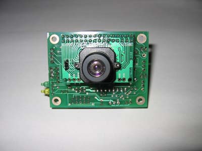
Pokey is supposed to be a budget/DIY robot. A couple weeks ago, I was considering a DIY vision system built around a cheap, poorly documented CMOS camera, but gave it up as too ambitious.
 Three remaining options best fit within budget and complexity constraints. Parallax has a 1d vision sensor (picture at right from http://www.parallax.com/) that captures a line at a time. By scanning across an area, one can reconstruct the complete image. Cost is considerably less than a 2d sensor at around $50 (and already I have spare servos).
One question arises: do I need to add an encoder like the one available from Acroname or this one from Zero One Mechatronics or make my own? Is a single servo step a small enough angle to reconstruct a complete image or is gear reduction needed for smaller steps?

The second option is to buy a $100 AVRcam kit which is simply a matter of assembling and then using. No reinventing the wheel, but not a lot of learning about computer vision, either. It may be worth the cost to save time. The vision system is totally open source, so future tinkering is entirely possible.
The third option is to use a black and white Game Boy camera.I've got one on order (Scratch that) One just arrived from eBay! There are several articles floating around about using this sensor. One in particular discusses interfaces to an AVR and external ADC. The camera can remain fixed on the robot and the robot can crudely scan the room as it is moving. However, implementation will be time consuming and complex.
Vision Processing Power
Video takes a lot of memory and processor speed. The Game Boy camera is based on a Mitsubishi M64282FP CMOS image sensor that, much like a human retina, has built in edge detection which is an amazing feature that offloads some intense image processing. It's only a 16KP -- that's right kilo-pixel -- camera: 128x123 pixels.
Even so, a maximum 30fps frame rate still puts a lot of demand on a mere MCU. The sensor is a serial device, outputting an analog value one pixel at a time. Maximum frame rate requires a 500KSPS (thousand samples per second) which is far beyond what most AVRs can provide with their built-in ADCs.
How much is really needed? For now, at least, simply taking a couple of still pictures might be enough to detect the candle flame, with a low frame rate to point the robot at the flame and drive to it accurately. So maybe 10fps is enough. Or less?
If one is to process just two entire frames in memory, one needs around 32K of RAM. There's probably little reason to process more than this yet. And maybe I can come up with some memory-saving tricks, like doing feature detection on the fly without storing the entire image.
Which MCU?
So what processor to use? Again, think low budget. Otherwise I should just get a CMUcam and be done with it. The ATmega8515, ATmega32, 64, and 128 can be hooked to as much as 64K of external SRAM. The AVR32 chips support 32K and 64K of internal ram. Sticking with AVR would save time. No new development environment, no new language. They're cheap, very few components to get one going, and no new serial programmer hardware to buy.
An external ADC could sample much faster than the AVR. I've got a couple of candidate ADCs I want to look at, one serial, one parallel. I'm leaning towards parallel as I think it'll be simpler to interface from a timing standpoint.
I've never looked at PIC processors before but there may be a couple of options there. For example, the PIC32XX3XX/4XX family runs at 80MHz, has up to 32K RAM and 1000kHz ADC sample rate. But, it would have the disadvantage of a new chip, new IDE, new flavor of C, etc. And I'd need to get a big TQFP breakout board.
Another option is to use a Parallax Propeller which runs at 80MHz, has 32K RAM and a little research suggests it may support fast ADC rates at lower resolutions (EDIT: the Propeller doesn't include an on-board ADC hardware peripheral, however it is possible to do 1-bit sigma-delta conversion). And it has parallel processing. It comes in a through-hole version as well as TQFP but requires several support components, particularly a serial EEPROM and a special usb-to-serial programmer. The unusual chip and its entirely new language would be very unfamiliar territory. Figure$40 ($23 as of Nov 15, 2011) for a Schmartboard development board, and try to hack one of my two usb-to-serial programmers for use with the Propeller. But, it runs about 160MIPS and does true, deterministic, real time parallel processing with 8 cores. That's a powerful argument.
Software
I'm not quite sure what the heck to do about software so more learning and experimenting is required there. This is one of those time vs money trade-offs -- with more investment I would save myself all the time of building circuits and software. But I wouldn't learn as much, either.
At any rate, the current plan is to prototype some algorithms on a PC or Mac using simulated candle images: pictures of a candle in various situations, re-sized to 128x123 pixels to see how feasible this really is. More on that in a later article.
Cheap Camera Options
Pokey is supposed to be a budget/DIY robot. A couple weeks ago, I was considering a DIY vision system built around a cheap, poorly documented CMOS camera, but gave it up as too ambitious.
 Three remaining options best fit within budget and complexity constraints. Parallax has a 1d vision sensor (picture at right from http://www.parallax.com/) that captures a line at a time. By scanning across an area, one can reconstruct the complete image. Cost is considerably less than a 2d sensor at around $50 (and already I have spare servos).
One question arises: do I need to add an encoder like the one available from Acroname or this one from Zero One Mechatronics or make my own? Is a single servo step a small enough angle to reconstruct a complete image or is gear reduction needed for smaller steps?
AVRcam picture at http://www.jrobot.net/
The second option is to buy a $100 AVRcam kit which is simply a matter of assembling and then using. No reinventing the wheel, but not a lot of learning about computer vision, either. It may be worth the cost to save time. The vision system is totally open source, so future tinkering is entirely possible.
The third option is to use a black and white Game Boy camera.
Vision Processing Power
Video takes a lot of memory and processor speed. The Game Boy camera is based on a Mitsubishi M64282FP CMOS image sensor that, much like a human retina, has built in edge detection which is an amazing feature that offloads some intense image processing. It's only a 16KP -- that's right kilo-pixel -- camera: 128x123 pixels.
Even so, a maximum 30fps frame rate still puts a lot of demand on a mere MCU. The sensor is a serial device, outputting an analog value one pixel at a time. Maximum frame rate requires a 500KSPS (thousand samples per second) which is far beyond what most AVRs can provide with their built-in ADCs.
How much is really needed? For now, at least, simply taking a couple of still pictures might be enough to detect the candle flame, with a low frame rate to point the robot at the flame and drive to it accurately. So maybe 10fps is enough. Or less?
If one is to process just two entire frames in memory, one needs around 32K of RAM. There's probably little reason to process more than this yet. And maybe I can come up with some memory-saving tricks, like doing feature detection on the fly without storing the entire image.
Which MCU?
So what processor to use? Again, think low budget. Otherwise I should just get a CMUcam and be done with it. The ATmega8515, ATmega32, 64, and 128 can be hooked to as much as 64K of external SRAM. The AVR32 chips support 32K and 64K of internal ram. Sticking with AVR would save time. No new development environment, no new language. They're cheap, very few components to get one going, and no new serial programmer hardware to buy.
An external ADC could sample much faster than the AVR. I've got a couple of candidate ADCs I want to look at, one serial, one parallel. I'm leaning towards parallel as I think it'll be simpler to interface from a timing standpoint.
I've never looked at PIC processors before but there may be a couple of options there. For example, the PIC32XX3XX/4XX family runs at 80MHz, has up to 32K RAM and 1000kHz ADC sample rate. But, it would have the disadvantage of a new chip, new IDE, new flavor of C, etc. And I'd need to get a big TQFP breakout board.
Another option is to use a Parallax Propeller which runs at 80MHz, has 32K RAM and a little research suggests it may support fast ADC rates at lower resolutions (EDIT: the Propeller doesn't include an on-board ADC hardware peripheral, however it is possible to do 1-bit sigma-delta conversion). And it has parallel processing. It comes in a through-hole version as well as TQFP but requires several support components, particularly a serial EEPROM and a special usb-to-serial programmer. The unusual chip and its entirely new language would be very unfamiliar territory. Figure
Software
I'm not quite sure what the heck to do about software so more learning and experimenting is required there. This is one of those time vs money trade-offs -- with more investment I would save myself all the time of building circuits and software. But I wouldn't learn as much, either.
At any rate, the current plan is to prototype some algorithms on a PC or Mac using simulated candle images: pictures of a candle in various situations, re-sized to 128x123 pixels to see how feasible this really is. More on that in a later article.
Friday, March 12, 2010
Pokey V2.0

Pokey's defeat in 2008 has nagged at me for the last couple years so time permitting Pokey and I are going to take another crack at it.
Pokey needs a refit and redesign. Here are some of the topic areas I'll be covering in the near future --
-- but first, what won't change?
No Dead Reckoning
You may recall that Pokey does not use dead reckoning. I want to continue with that design philosophy. Pokey relied on wall following and "events" to navigate -- the appearance/disappearance, while moving, of walls and floor markers.
Smooth Speed
Pokey was always intended to be a fast robot. His name comes from the fact that I had to slow him down before the original competition to increase navigation reliability. I don't want to slow him down further. If anything, I'm hoping to speed up the little fella. Also, Pokey was built to move smoothly and fluidly through the maze and I don't want to change that, either.
Budget
Pokey was intended to be somewhat low buck, with cheap, minimalist solutions preferred over fancier, more expensive ones where possible. I may have to admit defeat in a few areas and throw some more money at the problem, but I still want to come in under the cost of a Lego NXT when all is said and done.
Despite the things that won't change, clearly some changes are needed for Pokey to complete his mission and these things will be the subject of upcoming articles.
Navigation Problems

The wall following system was marginal. It could usually maintain a correct alignment but failed to correct even moderate misalignment. A single wall distance sensor was inadequate given short maze walls and a fast robot. A pair of wall distance sensors on each side should solve several problems at once.
While executing consistent, constant radius turns wasn't too tough, reliably turning to a precise heading was. The trigger to terminate the turn was the distance of the wall that the robot was turning to. It just didn't work.
I suspect using either a rate gyro or wheel encoders -- just for turning, not dead reckoning! -- would provide more precise heading changes and fluid movement. If I can actually pull it off, be assured you'll hear about it here...
Some robots had success aligning to the regulation door threshold floor stripe. This approach alters the flow of robotic movement as it enters the room, but maybe I can live with it if the gyro and encoder options don't pan out.
Flame Detection Problems
Pokey failed to detect a flame the one time he encountered the candle in the contest. I ran out of time to really dial in the calibration and software. The sensor itself works ok at closer ranges, poorly at long range. It's big and heavy, limiting fire suppression system options and making Pokey less nimble.

Picture from superdroidrobots.com of Hamamatsu UVtron
Affording (or justifying the cost of) a UVtron or Eltec Pyroelectric flame sensor -- or a CMUcam or NXTcam vision sensor -- is tough. The AVRcam is more affordable and, apparently, just as capable as these other two vision systems. Or sticking with some form of IR detection is still a possibility.
I'm currently exploring some cheap DIY camera/video options. I really think that's the best way to go since the last contest winner was using an NXTcam and very easily and reliably detected the candle. Not to mention, I could reuse this type of sensor for many other purposes. More on vision in future articles.
Telemetry
One of the biggest difficulties was that Pokey didn't collect data for later analysis. I never quite knew what the robot was doing from moment to moment. I'm working on using bluetooth-based communication for telemetry reporting and logging. More on this in an upcoming series of articles.
Collision Avoidance
Finally, it'd be nice if the robot could priority override all other functions to prevent head-on wall collisions...
Of course the biggest challenge is time... but at least I don't have to start totally from scratch.
Friday, February 19, 2010
Pokey Broke
Pokey's broken. The heat of firefighting competition a couple years ago--accidentally bashing into walls at full speed in particular--left Pokey's otherwise excellent Tamiya Double Gearbox in sad, noisy shape. A quick exploratory surgery revealed that both plastic 8-tooth (8T) pinion gears are cracked. Rats.


Fortunately, Tamiya has an inexpensive replacement set of plastic and metal pinion gears, TAM15289, Mini 4WD 8T Metal and Plastic Pinion Gear Set. Cool. The set I ordered arrived a few days ago and after installation, Pokey's geartrain is restored to full, smooth, silent health. Next up, equipping the plucky little robot with bluetooth remote control and telemetry capability. Articles to follow.
Incidentally, there are other pinion gear alternatives. You'd need a 48 pitch, 8T pinion gear for 2mm shaft. I don't know how to measure pressure angle or pitch diameter, so I guess you'd have to experiment such as with gears from this web store or maybe this one.

Pokey in pieces; broken, purple pinion gear

Pinion gear crack is on left, runs parallel to shaft
Fortunately, Tamiya has an inexpensive replacement set of plastic and metal pinion gears, TAM15289, Mini 4WD 8T Metal and Plastic Pinion Gear Set. Cool. The set I ordered arrived a few days ago and after installation, Pokey's geartrain is restored to full, smooth, silent health. Next up, equipping the plucky little robot with bluetooth remote control and telemetry capability. Articles to follow.
Incidentally, there are other pinion gear alternatives. You'd need a 48 pitch, 8T pinion gear for 2mm shaft. I don't know how to measure pressure angle or pitch diameter, so I guess you'd have to experiment such as with gears from this web store or maybe this one.
Friday, August 1, 2008
What Happened?
 I had some sad news here recently and so haven't been in a frame of mind to post but am doing better now.
The Science & Robot Expo did occur as planned, and Pokey did make an appearance... but like most of the other robots, wasn't really ready, so we didn't do a formal firefighting competition and ended up just hacking on the robots a little bit.
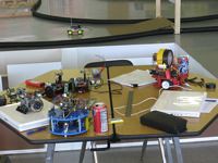
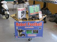
Unfortunately turnout was a little bit light, but the kids that did show up were treated to some really neat displays--- of college projects, of 3d printed objects, robot football, kids-focused robotics, RC, and more.
Friday, July 11, 2008
Noodlin'
Thinking through the navigation stuff... was thinking maybe it'd help to have steering correction that is non-linear with regard to the distance to the wall. Thankfully Grapher on the Mac makes it easy for a guy like yours truly to visualize some possibilities. I don't have it worked out and won't before tomorrow.
Rather than working out some complex equation, maybe a simple lookup table is easiest to concoct. What I'd want is minor steering correction (extremely long radius turn, so a small ratio of left to right speeds) for, let's say up to ±2cm distance, with increasingly harder (higher ratio left to right, shorter radius) turning for up to ±10cm distances. Beyond that, a routine that stops, searches for the wall angle, drives perpendicular to the wall and stops within the right range.
The other thought is, when you're driving a car and you want to change lanes, you don't just turn and hold your steering wheel. You turn it until you are starting to change direction at the rate you want, then you center the wheel, then turn in the opposite direction when you get into the correct lane. In correcting (especially large) distance to wall error, the robot should turn to correct distance errors but stop turning as it approaches a maximum rate of change in error, then turn the opposite way as the distance error grows low enough, seeking both 0 rate of change and 0 error. How would I get all this to work? I don't know for sure.
What I do now for sure is that once again I have no time to finish. Didn't this happen last time? A midterm that showed up right at the same time as the robotics contest? Hmph. So much for vindication... :)
So, will run Pokey as-is. I know he can get to the hard room with moderate consistency. I don't know if he can make it to room #2 let alone #3. #4 is right out. The candle scanning routine is no better than it was when it failed miserably last time. Ah well.
There's always next time :)
Meanwhile, the robotics expo / contest is going to be a LOT of fun with some cool vendor attendees and lots of robots to look at. Really looking forward to it!
Wednesday, July 9, 2008
Hacking Session #1
Spent a couple hours in the garage hacking on Pokey to try and improve the wall following. While it is working better, it isn't quite dialed in. Probably the right way to go is to self-calibrate to a target wall distance, hold that while wall following, and execute constant radius turns to maintain that distance within some small error range. That'll take time that I may not have...
One problem, which George M. astutely pointed out at a SHARC meeting many months ago, is that when the robot turns at too steep an angle to the wall, the angle of the sensor to the wall increases dramatically, affecting the accuracy of the distance measurement. So avoiding steep angles is helpful but difficult if the robot gets significantly off course and has short runs of wall. He did have a solution for this issue that I may explore.
As time permits today I'll noodle this over some more and see if I can come up with better solutions. I still think the wall following is key. If the robot can align to a wall and keep a set distance, navigation gets much, much more reliable.
Monday, July 7, 2008
Less than One Week!
Less than one week remains before the autonomous robot firefighting rematch on July 12! It's part of a cool robot Expo with vendors and other competitions.
Unfortunately, I've spent absolutely no time on Pokey in the last few weeks. I just got back from the hardware store with some fiberboard that I'll be turning into a full scale replica of the firefighting arena so I can get crackin' on Pokey's code over the next handful of evenings after work. Along with working on a midterm and course project, and prepping the Jeep for the big trip in two weeks.
Well, here goes, the old college try, the last minute hacking, try to pull it all together just in time. Stay tuned to see how it goes. Your guess is as good as mine!
Sunday, June 8, 2008
Firefighting Part II
The date is set! July 12 is the date of the next chapter in the autonomous robot firefighting saga! SHARC is putting on the contest this time. Can't wait to give it another go. Pokey is looking forward to a chance at redeeming himself from his embarrassing defeat in Ft. Collins.
As before, time is the enemy. School's back in swing (I thought I got the summer off, but noooo) and I have to get the Jeep ready for a big trip to Ouray by July 16. So fine tuning Pokey may be a bit tough to squeeze in, but hey, what else is new?
As before, time is the enemy. School's back in swing (I thought I got the summer off, but noooo) and I have to get the Jeep ready for a big trip to Ouray by July 16. So fine tuning Pokey may be a bit tough to squeeze in, but hey, what else is new?
Tuesday, April 29, 2008
Pokey's Famous!
 If you check out the latest issue of Robot Magazine you'll find that the Fort Collins robot firefighters are now famous! Pokey has his picture in the magazine, too ... along with some goofy guy.
Great articles by George M on the contest and his winning robot. Pokey's real glad to be in the magazine... but he wants a rematch!
I've been busy with my Jeep, work, and midterms, but when I get a second I'll share some more about Pokey's software. Stay tuned...
Sunday, April 13, 2008
Pokey's Software: Part 2
Most of the entrants used dead reckoning to navigate the firefighting maze, using Lego NXTwheel encoders built into the motor modules. The dimensions and layout of the maze are known (approximately) beforehand. Note that if you build the maze it doesn't quite look like the drawing.
 Pokey was designed to run through the maze without using dead reckoning. Instead, the little robot looks for what I call "events" such as the appearance of a wall to the left or right. The disappearance of the wall on the right or left. Detecting a floor mark. Of course these events are based on lower level sensor code that we'll get to in future posts.
Most importantly, navigation relies very heavily on good wall following because staying oriented to a wall means Pokey knows where he is in his predictable little world. And, in fact, poor wall following performance resulted in his humiliating defeat. :) But more on the low level stuff later. Here's a rundown on the high level event based navigation functions in nav.c
First off, here's the code that gets Pokey from home circle to the floating room. This code is in the main module, sparky.c
//////////////////////////////////////////////////////////////////////
// Home to Room A //////////////////////////////////////////////////////////////////////
go_straight(NAV_EVENT_WALL_HERE, LEFT);
wall_follow_left(NAV_EVENT_WALL_GONE);
myevent = corner_turn(NAV_EVENT_FLOOR|NAV_EVENT_WALL_FOUND, LEFT, LEFT, TURN_FACTOR * 0.80);
if ((myevent & NAV_EVENT_FLOOR) == 0) {
wall_follow_left(NAV_EVENT_FLOOR|NAV_EVENT_FRONT);
}
// Only way to align to the wall, for now
wall_follow_left(NAV_EVENT_FRONT);
stop_moving(); // Don't delete this you goon!
Pokey wants to follow the wall for the floating room to his left. But that wall doesn't appear right away, so Pokey drives forward looking for the wall to the left. His ranger array points left (second parameter below) and he takes off...
go_straight(NAV_EVENT_WALL_HERE, LEFT);
This routine drops out as soon as the wall is found. Now all he has to do is follow the wall until it disappears again.
wall_follow_left(NAV_EVENT_WALL_GONE);
Now he knows that he's in the middle of the maze and all he has to do is turn left into the first room using a constant radius turn (yes, we could use wall following but I found my way was easier to predictably achieve the proper distance once the robot has turned through 180°).
myevent = corner_turn(NAV_EVENT_FLOOR|NAV_EVENT_WALL_FOUND, LEFT, LEFT, TURN_FACTOR * 0.80);
Once Pokey either (a) crosses the floor marker at the door threshold or (b) finds the wall to the left after having made his 180° turn, we move onto the next step. If we still haven't found the floor marker, well, let's find it:
if ((myevent & NAV_EVENT_FLOOR) == 0) {
wall_follow_left(NAV_EVENT_FLOOR|NAV_EVENT_FRONT);
}
Ok, now Pokey knows he's in the room and that the wall is to the left. Pokey can then orient himself square to the room by relying on wall following that left wall until he gets to the corner-- when a wall appears dead ahead.
wall_follow_left(NAV_EVENT_FRONT);
Now Pokey can scan the room in a predictable fashion (more on that later), winding up either pointed at the candle if there is one, or pointed 180° opposite of how he came in--almost perfectly to leave the room. And since he's in the corner, he has a good stretch of wall to follow to reorient himself perfectly on the way out of the room. This is the same approach I used for every room.
That's the theory, but if you look at the video you'll notice he never makes it to the corner. Pokey doesn't straighten out fast enough after detecting the wall to the left and ends up continuing his turn until he is pointing at a sharp angle into the left wall. He sees the left wall in front of him and mistakes that for being in the corner. Oops.
Fortunately, the scanning routine works so well at orienting him that he's still able to navigate out of the room to the next one at least some of the time.
stop_moving(); // Don't delete this you goon!
During testing I would add stop_moving() calls to pause him at various places in the code so I could visibly troubleshoot what was happening. I'd forget and take out this call, too, and so he'd enter the room and run smack into the corner wall. So I wrote myself a little reminder.
From event.h here are the nav events
#define NAV_EVENT_NONE 0x00 // disables the event check
#define NAV_EVENT_WALL_GONE 0x01 // wall disappears
#define NAV_EVENT_FRONT 0x02 // wall appears in front
#define NAV_EVENT_FLOOR 0x04 // floor mark detected
#define NAV_EVENT_WALL_FOUND 0x08 // wall appears
#define NAV_EVENT_THIN_WALL 0x10 // unused, unneeded
#define NAV_EVENT_SHORT_FRONT 0x20 // wall close in front
#define NAV_EVENT_WALL_HERE 0x40 // wall close
#define NAV_EVENT_ALL 0xFF // all events, unused for now
The navigation event routines take one of these events to "watch for" and once found they drop out. The event type is a bit field, each bit corresponds to an event. So your routines can report multiple events at the same time. Each one of those nav event routines calls this one to watch for events. I threw in some addition comments:
event event_check(void)
{
event myevent = NAV_EVENT_NONE;
get_distances();
// Ranger pointing right?
if ( Pointing == RIGHT ) {
// Is the wall within wall following range?
// do we need to add a little fudge factor to distance?
if (distance_right <>
myevent |= NAV_EVENT_WALL_FOUND;
// Has the wall gone away?
else if (distance_right > 550.0)
myevent |= NAV_EVENT_WALL_GONE;
}
// if ranger is pointing left
else if ( Pointing == LEFT ) {
// Is the wall within wall following range?
// do we need to add a little fudge factor to distance?
if (distance_left <>
myevent |= NAV_EVENT_WALL_HERE;
if (distance_left <>
myevent |= NAV_EVENT_WALL_FOUND;
// Has the wall gone away?
if (distance_left > 550.0)
myevent |= NAV_EVENT_WALL_GONE;
}
// Object ahead, probably at end of hall or something
if (distance_front <>
myevent |= NAV_EVENT_SHORT_FRONT;
}
// this number is kind of fudged, trial and error
if (distance_front <> myevent |= NAV_EVENT_FRONT;
}
// Crossed over something white
if (floor_detected()) {
myevent |= NAV_EVENT_FLOOR;
}
return myevent;
}
You can see there's some dependency on the lower level sensor routines (ranger, floor sensor). Anyway, here's an example of one of the nav event routines:
event wall_follow_right(event wanted)
{
event myevent = NAV_EVENT_NONE;
look_right(); // point the ranger right
// drops out when the desired event is found
while ((myevent & wanted) == 0) {
// find out the distances
range_error = target_distance - distance_right;
range_error_rate = last_range_error - range_error;
// wall correction is a PID type routine based on
// current distance error and rate of change of error
steer = -(WALL_CORRECT());
// limit steering, or if we get too far away the bot will just spin
if (steer < -30) steer = -30;
if (steer > 30) steer = 30;
// record error statistics
last_range_error = range_error;
move_forward(MAX_SPEED, steer);
// Add discovered events to myevent
myevent |= event_check();
} // while
return myevent;
} // wall_follow_right
There's plenty more I could talk about but I don't want a 50 page post, either. For example, momentum and stopping distance: the threshold for detecting the front wall has to depend on speed.
The code has plenty of opportunity for improvement and generalizing to account for different speeds, battery voltages, etc. Reworking the wall following to incorporate constant radius turns would be swell.
Hopefully you get the gist, and I hope you found this useful.
Subscribe to:
Posts (Atom)