Showing posts with label vision. Show all posts

Friday, March 28, 2014

My Pixy arrived in the mail!


Well, can't wait to play with my just-delivered Pixy cam! Meanwhile I hope to finish OpenMV Camera assembly soon so I can demo at Robotics At The Hangar here in Denver on April 13.


Wednesday, February 12, 2014

OpenMV: low cost, hackable, scriptable machine vision

Introduction

OpenMV Cam will be the most hackable, low cost machine vision platform out there, because Ibrahim and I want to change the nature of hobby and educational robotics.

OpenMV Cam will be low cost; you can write scripts in Micro Python and a friendly IDE that run on the module controlling machine vision algorithms. The module supports Serial, SPI, and I2C, USB streaming for integration into robots or your desktop. It's easily hackable, based on the popular STM32F4, easily programmed with an open source toolchain; we can easily write our own software for it.

OpenMV Cam Is Available

And you can help. We're producing a short run of OpenMV Cam modules on Tindie so folks can help us add the final polish to the software. Eventually we'll do a fundraiser campaign. The firmware and IDE are pretty far along, actually. As of 9/16 we're in the process of assembling OpenMV Cam modules. You can backorder them on Tindie. Nobody gets charged until they are ready to ship.

Demonstrations

Imagine the projects you could build using 25fps face detection. An automatic bathroom mirror light, perhaps? Or automatically ring the doorbell when someone is at your door. Here's a video of using a Viola-Jones classifier for face detection to identify a face, then using FAST/FREAK to track the face regardless of scale and rotation. This is Ibrahim in the video. The video shows the IDE in action with the processing being handled by the OpenMV Cam.


What if you could do 60fps multi-color blob detection? Buy two and build stereo blob tracking? Laser scanning? Sort M&M's like a boss? Flame detection for Trinity competitions? More? This video shows blob detection as seen in the IDE with the camera module doing the processing.


Imagine what hobby electronics--or STEM education--will become when machine vision is as affordable as an Arduino?  Imagine the things we could do together, the problems we could solve.

Here's a video with the OpenMV Cam hooked up to an LCD to stream video. It'll also save video to the microSD card, and stream it to the computer as you saw above.


Join The Community

We're looking to build a community and we'd like you to join our Google Group.

Micro Python

You'll be able to script it in Micro Python, a lightweight Python for MCUs. It loads scripts off the microSD card. Some bindings are in place with full control in the works.

There's an IDE you can use with the camera that has a Python shell, a frame buffer viewer and you can use it to run scripts, save them to flash.


Also, for more flexibility, you can use several OmniVision sensors on this board: the 0.3MP OV7660, the 1.3MP OV9650/OV9655, and the 2MP JPEG OV2640. It's the latter sensor we like best and which ships with the OpenMV Cam on Tindie.

Hackable Microcontroller

What have you always wanted your machine vision system to do? Because it's running a widely known STM32F4 single core MCU, you can write and flash and debug your own firmware using an open source toolchain, CMSIS, and STM's handy Standard Peripheral Library.

There's already a growing community of support around this chip family with Pixhawk, STM32F4 Discovery boards, and more.

We're presently using an STM32F407 running at 168MHz using the native camera interface. Ibrahim has experimented with overclocking to 240MHz.

Algorithms

The OpenMV currently implements multi-object, multi-color blob tracking, Viola-Jones, Haar cascades (easily convert from OpenCV), and FAST + FREAK algorithms. You can use these to do relatively high frame-rate face and object detection.

Fundraiser

We'll be doing a fundraiser (Kickstarter, Indiegogo, or something along those lines) in the future. For now we'd like to involve you in the community and put some polish on the software.


Tuesday, January 22, 2013

LifeCam HD-6000 autofocus fix, Raspberry Pi

LifeCam HD-6000 autofocus fix

The Microsoft Lifecam HD-6000 autofocus is notoriously annoying. It refocuses unnecessarily sometimes every few seconds making the camera nearly unusable. Here's the workaround on Raspbian (Debian) for the Raspberry Pi.

Friday, September 17, 2010

Arduino / AVR Analog Comparator

As you may recall, I was working on detecting a candle flame using a Game Boy camera interfaced to an ATmega328P (in the form of a Solarbotics Ardweeny) coded in the Arduino IDE.

The AVR's onboard analog-to-digital converter is very slow. Too slow even for very low resolution (128x123) image capture. Frame rate was around 0.25 - 0.5 fps (that's one frame every 2-4 seconds).

Instead of adding an external ADC (I'll try that later), the simplest option for speeding up the frame rate was to use the MCU's built in analog comparator. Since the system only had to detect a bright spot, an 8-bit greyscale capture was unnecessary.

The AVR comparator sets one of the register bits high if the input voltage (typically the AIN1 pin) exceeds the reference voltage (the AIN0 pin) and sets it low if not.

Doing so takes a measly 1-2 clock cycles. At 16MHz that's 0.125 µsec, which is several orders of magnitude faster than the ADC.  For example, using the Arduino analogRead() function takes 100 µsec.  To maximize the frame rate there was a few more tricks to implement.  But first...

AVR Analog Comparator

Here's how to use the basic features of the AVR analog comparator. The AVR has two pins, AIN0, the positive input for the comparator and AIN1, the negative input. Optionally you can use any of the other ADC pins for the negative input, but let's focus on the simple solution, using AIN1.

To set things up (don't panic, code will follow shortly)...
  • Set up the AIN0 (PD6) and AIN1 (PD7) pins for input
  • Enable the ADC -- and/or set ADEN (ADC enable) in the ADCSRA register
  • Enable the comparator -- clear ACD (analog comparator disable) in the ACSR (analog comparator control and status register)
  • Disable the comparator multiplexer -- clear ACME (analog comparator multiplex enable) in the ADCSRB register.
  • Disable interrupts for the analog comparator -- clear ACIE in the ACSR.
The simple answer is to set all three registers' bits to 0 except set ADEN which I presume allows you to continue to use the ADC normally if needed.  Here's the C code:

  // Initialize Comparator - obviously this is done differently for AVR
  pinMode(6, INPUT);
  pinMode(7, INPUT);

  // ACD=0, ACBG=0, ACO=0 ACI=0 ACIE=0 ACIC=0 ACIS1, ACIS0
  // - interrupt on output toggle
  ACSR = 0b00000000;
  // ADEN=1
  ADCSRA = 0b10000000;
  // ACME=0 (on) ADEN=0 MUX = b000 for use of AIN1
  ADCSRB = 0b00000000;


Using the comparator substantially increased frame rate... to about 1 fps. But it was still a little too slow, primarily because of the object detection being performed on the AVR.

The Final Tricks

A high frame rate, or even 10fps would've been nice to achieve. But for purposes of aiming the firefighting robot at a candle, a sad 3 fps was acceptable.

Getting to that level of "performance" involved code tuning, which consisted of reducing and optimizing the machine code between the clock pulses sent to the camera, and reducing the size of the code as much as possible, and finally eliminating parts of the code.

Simple Machine Code Optimization
My simple process for optimizing machine code of compiled Arduino source is as follows:
  • Compile within the Arduino IDE, 
  • Generating an assembly file from the command line (Cygwin in this case
  • Count instructions and look at data references. 
  • Change code to try and reduce instructions
  • Change the way data is referenced (e.g., several arrays or array of struct; copy point to local variable)
  • Repeat process to see if changes reduced the instruction count

Nothing sophisticated, mind you. Just a question of trying different ways to reference data structures and write code that reduced assembly instructions.  This helped a little.

To do it, you'll need to run the avr-objdump command on the elf file generated by the Arduino IDE compiler. The elf file can be found in the applet subdirectory of your project.  The command to run is:

avr-objdump -S project.cpp.elf > project.S

You can then edit the .S (assembly) file to count instructions. Source code appears as comments in the assembly file to make it easier to locate relevant code.  For example:

// Continue reading the rest of the pixels and flood fill to detect bright objects
// The camera seems to be spitting out 128x128 even though the final 5 rows are junk

  for (y = 0; y < 123; y++) {

    if (y < 16)
     972:       10 31           cpi     r17, 0x10       ; 16
     974:       10 f4           brcc    .+4             ; 0x97a <__stack+0x7b>
      sbi(CAM_LED_PORT, CAM_LED_BIT);
     976:       5d 9a           sbi     0x0b, 5 ; 11
     978:       01 c0           rjmp    .+2             ; 0x97c <__stack+0x7d>
    else
      cbi(CAM_LED_PORT, CAM_LED_BIT);
     97a:       5d 98           cbi     0x0b, 5 ; 11
     97c:       24 2f           mov     r18, r20
     97e:       50 e0           ldi     r21, 0x00       ; 0
     980:       71 e0           ldi     r23, 0x01       ; 1


The big difference came when I eliminated the part of the object detection code that attempted to merge nearby objects on the fly during capture. That work is now done after the image is captured and object coordinates are generated. The approach worked reliably and improved frame rate considerably.

Conclusion

I felt I hit a wall in speeding up the code and put it on the back burner for awhile.  Working up to a 5 or even 10 fps frame rate with an AVR seems like a daunting task.  Let alone the 20-30fps some robotic camera systems can achieve.

I am contemplating a processor upgrade, instead of more attempts at optimization. I recently purchased a Parallax Propeller to play with. Another possibility is an inexpensive ARM processor I ran across.

I would like to try using the camera for robust object detection and avoidance and that, most likely, will require greyscale capture.  I have a few fast ADCs to experiment with if the ARM or Propeller can't hack it.  Even without greyscale, vision-based object avoidance will need a much higher frame rate.

Friday, May 7, 2010

Vision-Based Candle Detection

Updated 9/9/2010: Source Code is now available on Google Code.

The Cliffhanger

Having previously interfaced a Game Boy camera to an AVR (Ardweeny / ATmega328P) and successfully capturing an image, the next step in detecting a candle flame was, well, detecting the candle flame.

Would the camera be able to capture an image of a distant flame? Would an IR filter work to block out everything but a source of flame?

For that matter, the flame detection software hadn't been tried on an actual Game Boy image yet. And the code hadn't been ported to the memory-constrained AVR yet either.

IR Candle Detection

Using exposed film as an IR filter I got good image results for a distant candle, below, sitting about 170cm from the lens, a typical distance in the real competition. The candle flame is left of center. The center bright spot is the candle's reflection in a glass-covered picture hanging on the wall (but, in the competition, mirrors cannot be placed in the same room as the candle).

The captured image

I added a feature to the client software allowing me to save the captured picture to a file on the PC. Then I processed it into a BMP that my prototype flame detection program could read, and the program it spit out the data for the real candle. It worked!

The detected object

Running Detection Code on the AVR

The flame detection software would have to run on the robot so I redesigned the code to fit into the tiny 2K of RAM on the ATmega328P.

Recall that the software essentially performs a flood fill on every pixel brighter than a set threshold. Since it's only purpose is to spit out a set of bounding boxes around detected objects, it really doesn't need to remember the entire image or the flood fills (assignment of pixels to objects) already performed, just the object assignment for the current and prior rows' pixels, from which it can calculate the bounding boxes.

Code Details

The only reason the code needs to remember the prior row is to know if the pixel above the current pixel belongs to an object. Like so:

.. .. 01 01 01 .. .. 02 02 .. 03 03 03
01 01 01 01 01 .. .. 02 02 .. .. 03 ..

It turns out that we never need to look more than one row above, so we only need to keep two rows of object assignments. That's an array of 2 rows, and (in the case of the Game Boy camera) 128 columns.

With the added bonus that we can use a simple XOR operation to toggle back and forth between the two rows: the first time through, row 0 is current, row 1 is previous and the next time through, row 1 is current, row 0 is previous.

Here's the excerpted AVR C code that does the "flood fill".

For what it's worth all the camera and object detection code is just over 4K in size so there's no reason it wouldn't fit in a lower-end AVR.

The Results

Forgetting to take baby steps in program re-factoring, the first attempt was a disaster. The second attempt, however, wasn't.  I revised the client code to receive and display the bounding boxes in bright green...

Target Flame Acquired! Distance 185cm

Target distance 100cm

Detection worked well even without the IR filter.  With the filter, object detection will probably be more reliable. You'll notice some extraneous objects detected.  One is the candle's reflection in a glass holding the remains of an iced latte I made.  The other is... a reflection off the computer mouse, I think?  Of what, I don't know.

The vision-based detection has come along really nicely.  It's pretty darned close to usable right now. Without too much more work, I could hook up Pokey's Orangutan controller to the Ardweeny and it could request and retrieve detected objects and then do something with them.

What's Next?

One of the concepts in iterative development is to focus on solving the hard problems first and leave refinement and easy features for later.  I think that makes a lot of sense so I'm going to put the flame detection on the back burner and work on fixing Pokey's navigation problems.

But you won't hear about that for awhile. Instead, the next few articles will share the steps involved in proving out how to equip Pokey with a Bluetooth modem.

Updated 9/9/2010: Source Code is now available on Google Code.

Friday, April 23, 2010

GameBoy Camera Prototyping

Updated 9/9/2010: Source Code is now available on Google Code.

Holy TTL, Batman. My cobbled-together code and circuitry works! I just took my first Game Boy Camera picture.  Here are all the secrets I know of for interfacing a Game Boy Camera (Mitsubishi M64282FP) to a microcontroller.

First picture!

The actual scene

Summary Version

With Game Boy Camera, Ardweeny running tweaked version of code here, HP 1650A Logic Analyzer to get the timing right, Java Swing desktop application based on code here, and after fixing goofed up wiring and timing it works!  Some tweaking of camera configurations and it now takes some nice shots, and the flame detection software does its job with real images, too!

Really Important Tips
  • Timing is key when interfacing with the M64282FP
  • But, you can also clock the M64282FP as slow as you need to 
  • Setting the bias (dc offset) voltage to 1.0V is mandatory (the chip outputs 2Vp-p)
  • Setting the black level offset correctly is important
  • The camera actually spits out 128x128 pixels, but the last 5 rows are junk
  • Setting the gain too high can cause odd pixel artifacts (MSB truncation?)

The Long Version

Game Boy Camera
First, I cut wires off of the 9-pin connector, one by one, and spliced them to longer wires and attached each to a small breadboard with 9-pin header so I could plug the camera into my protoboard.

Microcontroller
The Ardweeny from Solarbotics that I recently ordered and assembled lends itself well to rapid prototyping. It's Arduino-compatible running an ATmega328P MCU.

The first step was getting the code put together and getting the timing signals right to activate the Game Boy Camera (Mitsubishi M64282FP image sensor chip aka "Artificial Retina").

I started with code here plus the datasheet. I copied the code into my Arduino IDE and tweaked it as necessary to get it to compile. Then tweaked some more to get the timing right. Along the way, I merged several functions so signal timing was more obvious to me as I read the source.

I ran the code, and... it didn't work. I wasn't getting any response from the image sensor... until I realized I'd crossed a couple of wires on the protoboard. Fixing that, the data came streaming through on the Arduino IDE Serial Monitor.  My Arduino code can be found here.

Mitsubishi M64282FP Timing
I've found two versions of the datasheet so far and the timing is a bit ambiguous so let me provide the following hints. If you're in the middle of working with one of these cameras, all this will mean something. Otherwise it won't...
  • RESET/XRST has to be low on the rising edge of XCK
  • Raise LOAD high as you clear the last bit of each register you send
  • START has to be high before rixing XCK
  • Send START once
  • The camera won't pulse the START pin; the datasheet is confusing about this
  • READ goes high on rising XCK
  • Read VOUT analog values shortly after you set XCK low
Logic Analyzer
In debugging and fixing the timing, the HP 1650A Logic Analyzer that I recently put in operation was absolutely invaluable. I can't imagine trying to debug the issues I encountered without a logic analyzer.

Ardweeny Under Test

Checking Signal Timing

PC Software
Next up, capture the serial data and display it as a picture on the screen. I started with code here and decided to take a dive into the NetBeans IDE. I like it so far. Lighter weight than Eclipse, more intuitive to use, and it has a really nice GUI designer built in. I found it rather familiar after having worked with Xcode while equipping Pokey with a Bluetooth modem (a series of articles coming soon).

I created a new project, designed a GUI from scratch using the IDE, then copied the relevant code into the appropriate spots. Did a few tweaks to get it to talk to the software on the Arduino.  Finally got an image to display on the screen--consisting only of lines and gibberish. Not the real picture. Crap!

The preliminary version of the M64282FP datasheet suggested the cause might be a timing issue when reading the analog pixel data. The datasheet I'd been using was ambiguous on that issue.

I tweaked the code to read Vout (analog) shortly after dropping XCK and... Shazam!  The image at the top of this article appeared.

After the time put in bashing through, seeing that image was nothing short of miraculous!  The source code and NetBeans project files for the PC client are here.

Configuring the Camera
Getting that first readable image was great, but the second one sucked, with bizarre artifacts where bright spots should appear (see below).

There's no way my simple bright-spot detection algorithm could correctly handle this mess of pixels. I had to learn more about how the camera settings worked.

Artifacts from high gain and MSB truncation

To help with troubleshooting, I extended the functionality of the client significantly, providing a means of setting the relevant camera registers and displaying a histogram below the picture.

One last article I found on the camera held a revelation. The Vout voltage is 2 volts peak to peak!  So one has to configure the voltage offset register V for 1.0V, a value of 7 per the datasheet, to get positive signals that the ADC can handle. Doing so immediately yielded a better result.

Then I discovered that the bright artifacts disappeared when setting the camera's gain above 0. It dawned on me that I am using a 10-bit ADC but passing an 8-bit value to the Java Application; I was truncating the most significant bits, which mattered at higher gains with higher maximum voltages. That explained everything.

I found that you can either continue to use the lowest 8-bits and set the gain to 0, or rotate off the lowest two bits, then increase the gain substantially, and possibly also tweak Vref and offset to maximize the dynamic range of the picture.. bottom line, just be careful of the resolution of your ADC and the data types (signed, unsigned, int, char, short) used to store the results.

The black level in the image is set by the offset register O in 32mV increments plus or minus. If the offset is too low, and the image is underexposed.  I had strange white pixel artifacts appear where the darkest parts of the picture are supposed to be. Setting the black level a little higher solved the problem.  Apparently the "negative" voltage values were being converted to an unsigned value and became high value pixels (white) which you can kind of see when you look at the histogram.

Offset Too Low + Underexposed

Using the histogram feature made it easy to quickly dial in a decent exposure. Ideally, software auto exposure would be great, but for the narrower purpose of finding the candle, manually calibrating the camera for competition conditions will probably be adequate.  Depends on how much time I have for refinement.

Correct Exposure... Finally!

So does it work?  Can the camera see a candle?  Does the flame detection software work?

Nothing like a blogging cliffhanger, huh?  Click here to find out what happened.

Updated 9/9/2010: Source Code is now available on Google Code.

Friday, April 9, 2010

Candle Seeking Vision Software

Pokey, the firefighting robot, absolutely must find the candle this time!  Not like last time when he completely ignored the candle right in front of him. (sigh)

While waiting for a 
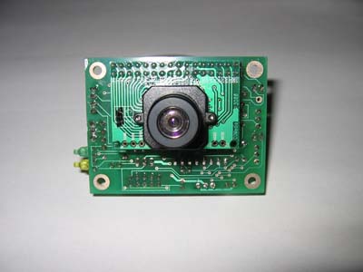
Game Boy camera to show up in my mailbox, I figured I better see how hard it would be to cook up some code that could reliably detect a candle at various distances.

So the next proverbial bite of the elephant was to do some code prototyping in an environment that's comfortable and easy.  To wit, C in Cygwin on my PC (yes despite all my posts referencing Macintosh, and a house full of them, I have--and use--a PC, too, because it was faster than my G4/450 and it cost $5).

Simulating Pictures
The Game Boy camera outputs 128 x 123 pixel, 8-bit grayscale images.  To simulate contest scenarios, I shot pics with my DSLR of a candle in various spots around the room, uploaded them, then batch converted the images using Irfanview to approximately 128x123 pixels, 8-bit greyscale, and saved as an easy-to-work-with Windows BMP (bitmap) file:

Greyscale 200x123 bitmap of candle

Reading a Bitmap File
Then I coded up a simple C program to reprint the BMP as ASCII art, to verify that I can access each and every bit and it's brightness value.  Of course, the aspect ratio is a little skewed but... clearly the program works!  (Click on the image for a much larger, clearer, and hopefully brighter version if you're skeptical).  I will hereby confess that my C skills were pretty rusty.  How could I forget the proper way to malloc() a char ** type??  That's just sad.  Perl has made me soft and weak...

Converted to ASCII art

Notice in the detail shot below, that the candle flame is, in fact, the brightest thing in the picture, represented by the character X (assigned to any pixel with a value greater than 240 out of 255); the next brightest thing is indicated by the character +, like the white candle, itself. Clearly the flame is the brightest thing in the picture. Cool!

Detail of candle; flame is brightest

So that tells me there is actually some hope of detecting bright spots in a snapshot image.  I didn't use any IR filtering, which "should" improve things even more by eliminating most everything in the image except the flame or reflected IR.

Some Difficult Scenarios
This test photo above represents an easy scenario.  I'll need to anticipate the possibility of multiple bright spots of different sizes: sun shining on a wall, or the reflection of the flame on the wall behind it.  The algorithm will have to key in on the brightest spots that are the size and/or proportions of a candle flame.

Candle flame and distant, sunlit door

If that happens, the robot will have to somehow evaluate each candidate candle flame. Maybe with other sensors, maybe by going up closer and taking another 'look'. The robot also has to be able to recognize a flame despite sizes varying in size, whether because of distance, drafts, length of candle wick, type of candle, or whatever the cause.

Candle flame and reflection off of HP LaserJet

Some Experiments
Now that I had the "lab" set up, it was time to experiment with some statistical analysis, perhaps try out some published algorithms for finding bright spots, or whatever else came to mind.

First, I plotted a histogram for each of the images. Roughly speaking, the bright pixels accounted for a pretty small percentage of the intensities represented in the images. My thinking is that histogram statistics might help to yield an optimal exposure so there's more work to do with that.  I'd rather wait on that until I have a better sense of what the camera sensor can do.

Next, I tried simply projecting (summing) the bright spots vertically and horizontally. In the case of one bright candle object, this approach would yield a quick way to identify a bounding box around the object.

Prototyping Flood-Fill
Then I decided to play around with multiple object detection. After some research, the flood-fill algorithm caught my fancy.  It was simple enough to play with and hopefully could be efficient enough to support analysis of multiple objects at a reasonable frame rate (10-30fps). Here's what I did.

The image from the camera will be coming in serially. Likewise, my simple C program reads the bitmap pixels sequentially.

Scenario 1
A two-dimensional array of unsigned integers represents each pixel's object assignment. (Inefficient, but quick to prototype). When the code encounters the first bright pixel (above a set threshold) after one or more dark pixels, it assigns that pixel to the next available object number (essentially, object_mask_array[x][y] = nextavailableobj). All subsequent, contiguous bright pixels are assigned that same object number. Like this.

.. .. 01 01 01 .. .. 02 02 .. XX XX XX

The ".." is a dark pixel. The XX hasn't been processed yet. Two objects identified so far, and the final three pixels will be assigned to 03.

Scenario 2
That's the simple scenario. But if there's a bright pixel above the current bright pixel, the two are contiguous.  So whatever object was previously assigned to the pixel above should be assigned to the current one.  The simplest scenario follows.

.. .. 01 01 01 .. .. 02 02 .. 03 03 03
.. .. .. XX XX .. .. .. .. .. .. .. ..

When the first XX is encountered, it is contiguous to the pixel above, assigned to 01.  So the current pixel is assigned to 01 also, as well as all subsequent, contiguous bright pixels, like this:

.. .. 01 01 01 .. .. 02 02 .. 03 03 03
.. .. .. 01 01 .. .. .. .. .. .. .. ..

Scenario 3
If the above pixels 'start' before the bottom set of pixels do, it's easy. A harder scenario, below, occurs when one's already assigned an object to a row of pixels only to discover part way through that the line is contiguous with an object above.

.. .. 01 01 01 .. .. 02 02 .. 03 03 03
04 04 XX XX XX .. .. .. .. .. .. .. ..

The current pixel (leftmost XX) is contiguous with 01 above, but we've already assigned 04 to this object. Since I was only prototyping, my inefficient solution was simply to stop where I was and re-do the prior pixels.

.. .. 01 01 01 .. .. 02 02 .. 03 03 03
01 01 XX XX XX .. .. .. .. .. .. .. ..

And then I could continue assigning subsequent pixels to the 01 object.

.. .. 01 01 01 .. .. 02 02 .. 03 03 03
01 01 01 01 01 .. .. .. .. .. .. .. ..

Scenario 4
The hardest scenario, which I didn't address in my prototype code, was that of a pair of bunny ears. In other words, the object has two lumps at the top that are not contiguous themselves, but a subsequent row ties them both together. One has to go back and redo the object above.  Like this.

.. .. 01 01 01 .. .. 02 02 .. 03 03 03
01 01 01 01 01 01 01 XX XX .. .. .. ..

The 02 object has to be reassigned to the 01 object.  If it's just one row that isn't even all that hard.  But what if it's several rows.  And what if some of those rows 'start' earlier than the ones below?  You can easily come up with additional tricky situations.

.. .. .. .. .. .. .. 01 01 .. .. .. ..
.. .. .. .. .. .. 01 01 01 .. .. .. ..
.. .. 02 02 02 .. .. 01 01 .. 03 03 03
02 02 02 02 02 02 02 XX XX .. .. .. ..

This complexity is an artifact of processing pixels on the fly -- versus reading everything first, and processing after.  I wanted to see if the former approach was even possible in case the vision system turns out to be memory constrained.

Flood Fill Results
Once again this was just a proof-of-concept to see if there was any chance in the world that I might be able to identify separate bright objects in an image and the experiments successfully showed that it is possible even with a relatively simple algorithm.

Of course to do this 'for real' the algorithm would then have to keep track of the bounding box coordinates for each object and eventually some code would have to determine which objects were likely to be candle flames. All in due time.

A Difficult Scenario

At least for now I can take a pretty tough scenario like the above, with a candle in front of a sunlit door, and identify that the candle and the swath of sunlight are separate objects.  Click on the text image to see that the swath of light is assigned to object 05 and the candle flame is assigned object 03.

The Algorithm Works!

My astute readers will no doubt notice the lower left part of the swath of light is assigned to object 01.  The algorithm processes the bitmap pixels upside down, the order in which they're stored in the file. So it runs into the bunny ears scenario (4 above) and ends up assigning the second bunny ear to 05 then assigns the line connecting 01 and 05, and all subsequent lines, to object 05, leaving a the first bunny ear still assigned to object 01.

Bounding Box
Writing code to calculate the bounding box of each object was pretty straightforward.  The hard stuff was already completed (above).  A "C" struct represents an object and contains an "exists" flag to indicate if the object has been created or deleted, as well as bounding box coordinates for top, bottom, left and right.

One simple function adds a pixel to an object: if the pixel lies outside the bounding box, the box's coordinates are changed to encompass the new pixel.

A function to delete an object is called when encountering scenario 3 above. Pixels that were originally assigned to a new object are later discovered to be connected to a second object. This new object can be discarded because all of its pixels have to be reassigned to the second object.

Finally, a print function displays info about each object, including calculating size, aspect ratio and midpoint, and then printing out the bitmap within the bounding box.  Here's the results from the simple test image:

-------- Candle006.bmp --------
Width: 185 Height: 123 Planes: 1
BitCount: 8 Colors: 256 SizeImage: 23124

Object 02
  Box: (97, 66) (100, 60)
  Size: (4, 7)
  Ratio: 57%
  Mid: (99, 63)

....02..
..0202..
020202..
..0202..
..0202..
02020202
02020202

Recall that the y coordinates are upside down due to the BMP file format.The midpoint coordinates are for pointing the robot at the flame.  The width-to-height proportion may help filter out non-flame objects.  From here, I can add any other info or calculations that are needed, like average intensity within the bounding box.

Also, I could add pixel coordinates to each object struct to enable recreation of the original image or the bright/dark processed image without having to store the entire bitmap in memory.

Whee!
Maybe it seems silly but I'm incredibly excited that I got all this working. The vision approach is starting to look pretty hopeful...

...notwithstanding the mountain of electronics interfacing work yet to do...

Friday, March 26, 2010

Exploring Vision Options

As part of the Pokey refit for the next Firefighting contest, better flame detection is a must. Imaging seems the most reliable solution.  The NXTcam was probably a large part of Physignathus' victory in the first Fort Collins Robot Firefighting Contest.  The CMUcam is popular as well.  But both are too expensive for me.

Cheap Camera Options
Pokey is supposed to be a budget/DIY robot.  A couple weeks ago, I was considering a DIY vision system built around a cheap, poorly documented CMOS camera, but gave it up as too ambitious.

Three remaining options best fit within budget and complexity constraints. Parallax has a 1d vision sensor (picture at right from http://www.parallax.com/) that captures a line at a time. By scanning across an area, one can reconstruct the complete image.  Cost is considerably less than a 2d sensor at around $50 (and already I have spare servos).

One question arises: do I need to add an encoder like the one available from Acroname or this one from Zero One Mechatronics or make my own? Is a single servo step a small enough angle to reconstruct a complete image or is gear reduction needed for smaller steps?

AVRcam picture at http://www.jrobot.net/

The second option is to buy a $100 AVRcam kit which is simply a matter of assembling and then using.  No reinventing the wheel, but not a lot of learning about computer vision, either.  It may be worth the cost to save time.  The vision system is totally open source, so future tinkering is entirely possible.

The third option is to use a black and white Game Boy cameraI've got one on order (Scratch that) One just arrived from eBay! There are several articles floating around about using this sensor. One in particular discusses interfaces to an AVR and external ADC. The camera can remain fixed on the robot and the robot can crudely scan the room as it is moving.  However, implementation will be time consuming and complex.

Vision Processing Power
Video takes a lot of memory and processor speed.  The Game Boy camera is based on a Mitsubishi M64282FP CMOS image sensor that, much like a human retina, has built in edge detection which is an amazing feature that offloads some intense image processing.  It's only a 16KP -- that's right kilo-pixel -- camera: 128x123 pixels.

Even so, a maximum 30fps frame rate still puts a lot of demand on a mere MCU.  The sensor is a serial device, outputting an analog value one pixel at a time.  Maximum frame rate requires a 500KSPS (thousand samples per second) which is far beyond what most AVRs can provide with their built-in ADCs.

How much is really needed?  For now, at least, simply taking a couple of still pictures might be enough to detect the candle flame, with a low frame rate to point the robot at the flame and drive to it accurately.  So maybe 10fps is enough.  Or less?

If one is to process just two entire frames in memory, one needs around 32K of RAM. There's probably little reason to process more than this yet.  And maybe I can come up with some memory-saving tricks, like doing feature detection on the fly without storing the entire image.

Which MCU?
So what processor to use?  Again, think low budget.  Otherwise I should just get a CMUcam and be done with it.  The ATmega8515, ATmega32, 64, and 128 can be hooked to as much as 64K of external SRAM. The AVR32 chips support 32K and 64K of internal ram. Sticking with AVR would save time. No new development environment, no new language. They're cheap, very few components to get one going, and no new serial programmer hardware to buy.

An external ADC could sample much faster than the AVR.  I've got a couple of candidate ADCs I want to look at, one serial, one parallel. I'm leaning towards parallel as I think it'll be simpler to interface from a timing standpoint.

I've never looked at PIC processors before but there may be a couple of options there. For example, the PIC32XX3XX/4XX family runs at 80MHz, has up to 32K RAM and 1000kHz ADC sample rate.  But, it would have the disadvantage of a new chip, new IDE, new flavor of C, etc.  And I'd need to get a big TQFP breakout board.

Another option is to use a Parallax Propeller which runs at 80MHz, has 32K RAM and a little research suggests it may support fast ADC rates at lower resolutions (EDIT: the Propeller doesn't include an on-board ADC hardware peripheral, however it is possible to do 1-bit sigma-delta conversion). And it has parallel processing. It comes in a through-hole version as well as TQFP but requires several support components, particularly a serial EEPROM and a special usb-to-serial programmer. The unusual chip and its entirely new language would be very unfamiliar territory. Figure $40 ($23 as of Nov 15, 2011) for a Schmartboard development board, and try to hack one of my two usb-to-serial programmers for use with the Propeller. But, it runs about 160MIPS and does true, deterministic, real time parallel processing with 8 cores. That's a powerful argument.

Software
I'm not quite sure what the heck to do about software so more learning and experimenting is required there. This is one of those time vs money trade-offs -- with more investment I would save myself all the time of building circuits and software.  But I wouldn't learn as much, either.

At any rate, the current plan is to prototype some algorithms on a PC or Mac using simulated candle images: pictures of a candle in various situations, re-sized to 128x123 pixels to see how feasible this really is.  More on that in a later article.