 |
| Data Bus, April 2012 |
With only three sensors, a simple Kalman Filter, and a total cost of around $650, the robot was able to achieve a top speed of around 20mph, with a total raw time around the building of 37 seconds and a cross track error of ~1 meter for the 2012 AVC.
Step right this way and we'll begin the nickel tour of the robot, it's features, sensors, software, and more...
Chassis
Robotifying an RC Truck
The robot started as an ElectrixRC "Circuit" 1:10 stadium truck. At $130, it was the least expensive 1:10 RC truck I could find at my local RC Hobbies. But it's not cheap-o. It's tough, easily customized, good parts support, and has a loyal fanbase. ECX is a good value.
It runs a Tacon 3000Kv brushless motor, Hobbywing 35A ESC, 2.4GHz FlySky 3 channel receiver, and 2S, 4000mAH 25C Gens Ace LiPo battery, ElectrixRC 'hard' springs, and Traxxas Anaconda tires on 2.8" All Star black chrome wheels.
Suspension tuning completed the chassis work. I used 50wt oil in all four shocks, and adjusted ride height in back with springs inserted below the shock pistons. The result was a lower center of gravity and much flatter turns.
 |
| Brushless goodness |
Body
The body is a Parma PSE "Skool Bus" lexan body custom painted by yours truly with custom decals printed on inkjet self-adhesive paper and coated with automotive clear coat.Navigation and Configuration
Navigation is simply a matter of specifying waypoints in latitude and longitude. The robot converts to cartesian coordinates and navigates assuming that it starts at the first waypoint and is pointed directly at the second waypoint. From there it uses dead reckoning based on distance and heading.The robot uses a pure pursuit path following algorithm to follow a direct path between waypoints.
AVC path following
It makes a graceful turn when it gets close to its target waypoint. To that end, the configuration file specifies the braking distance and turning distance and a minimum turn radius. The configuration file specifies a default cruise speed and turn speed, as well a adjustments at each waypoint for both speeds.
The robot implements a PID loop to achieve the target speed, with user configurable P, I, and D constants, specified in the configuration file.
The configuration file also specifies a number of other parameters like wheelbase, track width, conversion factors for steering angle, as well as steering and ESC settings and more.
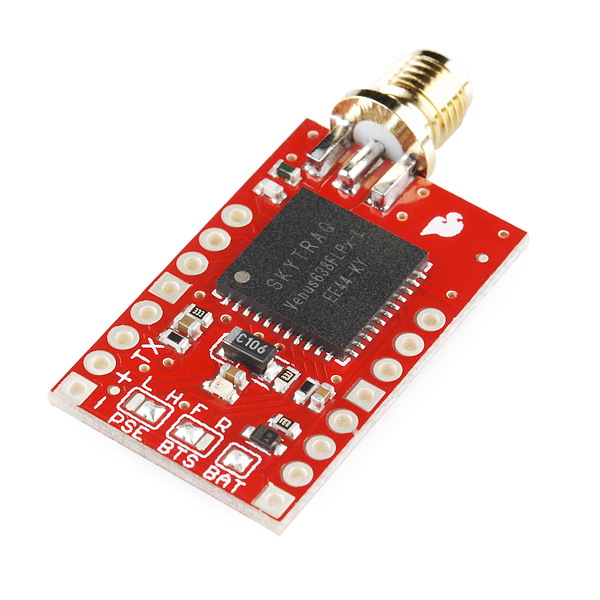 |
| My 2012 Venus GPS |
Sensors
Data Bus uses only three sensors. A Gyro, a GPS, and wheel encoders.GPS
The GPS is a 3DR uBlox LEA6-H mounted under the body roof with an aluminum ground plane that provides about 5-10db signal gain. The GPS communicates using uBlox binary protocol with the mbed MCU. The GPS only supplies heading information. Extensive testing demonstrated that GPS position information is best ignored.Gyro
Precision Gyro Calibration ReloadedAdditional heading information comes from an STM L3G4200D gyro on a Pololu minIMU-9, mounted on an aluminum bracket up front. Communication is via I2C at 400kHz. The gyro is sampled at 100Hz.
 |
| Redesigned encoder board |
Encoders
AVC: Wheel EncodersWheel encoders on both rear wheels provides accurate distance measurement. The 32-stripe wheel encoder discs were created with my WheelEncoderGenerator cross-platform java application.
Sparkfun QRE1113 sensor boards mounted to the bearing carriers sense the stripes and send signals to a Schmitt-trigger board I designed.
Experimentation, Simulation, Analysis
Why The Wrights Flew FirstMagnetometers and Motors
Magnetometer Calibration
Is a Compass Necessary?
Is a 3D Compass Necessary?
Magnetometer Calibration Error
Encoders and Quantization Error
In 2012, inspired by the Wright Brothers' scientific methodology, I spent many hours testing, modeling and experimenting to gain a clear understanding of sensor error modes and the resulting impact on position estimation error.
All that work led to my unorthodox but successful sensor choices, particularly eliminating the compass and using only heading data from the GPS instead of position. The three sensors are used to estimate position and heading, aka pose.

Pose Estimation
Heading and Position EstimationAccording to my calculations, heading is incredibly important in the Sparkfun AVC. An error of only a couple of degrees is the difference between crashing and finishing. The software on Data Bus includes a Kalman filter that finds gyro drift from GPS heading and gyro heading rate data. The error term is used to update the computed heading and position.
However, data from the GPS lags behind reality. In the case of the Venus GPS, the lag was around 600ms and for the uBlox about 400ms.
What's Wrong With Data Bus?
The gyro data must be time-lagged before comparing with the GPS data in the Kalman filter to get a good estimate that survives during maneuvers. In short, the gyro data is used to compute heading in near real time, and the historical gyro and lagged GPS heading information corrects for drift. The end result is a heading estimate with high dynamic range and negligible drift.
Meanwhile, distance traveled is given by the average distance of the wheel encoders. I calibrated the wheel encoders to Google Earth, my waypoint editor, and found the error falls below 1%.
The robot knows how far it's gone and in what direction, giving a position estimate. The position is estimated in cartesian coordinates to speed up computation, particularly when updating position based on gyro error. I can simply use a rotation matrix to correct position error due to heading error.
Microcontroller
Choosing an MCUBrain Transplant and Updates
 |
| LPCXpresso/mbed compatible RoverBaseboard |
I've converted to offline compilation for the mbed SDK which enables me to make code changes in the field, something I couldn't do at previous competitions.
In the near future I will investigate migrating to a 120MHz LPC1769 LPCXpresso. I've installed a new RoverBaseboard, pictured, that supports both mbed and LPCXpresso form factors.
User Interfaces
Data Bus Interfaces and ConveniencesAVC: Ground Control Station
AVC: Pose and Map Display
 |
| Sparkfun Serial Graphic LCD user interface |
A simple menu interface is provided on the built-in USB-to-serial adapter on the mbed. The menu gives access to instrument diagnostics, software reset, a unix-like shell for managing and downloading log files and a few other conveniences.
Finally, the robot features an onboard physical interface consisting of a Sparkfun 128x64 graphical LCD display and 3 buttons on the Bus body. At the starting line, with any form of remote communication prohibited, this interface is crucial for making sure the robot is ready and for commanding it to begin racing.
Data Logging
Logging Data to SD CardsData is logged as text CSV to an onboard FAT32 microSD card connected to one of the mbed SPI ports. Around 20 system state values are logged at a rate of 50Hz and typically take no more than 150usec to write but the logging is buffered and done in the non-time critical outer loop. Logfiles are named with sequential numbers.
Offline analysis scripts in Processing, perl, and Octave plot and visualize the sensor data, or prepare KLM files for display in Google Earth. The onboard shell command 'send' in combination with a customized Java serial terminal program initiates on-the-fly download of logfiles.
Power Supply
 |
| Lots and lots of wires... |
Wiring
All the wiring uses 0.1" pin headers and crimped and soldered female connectors on custom cables, all consistently color coded to eliminate race day goofs. I've learned that loose connections and rats nests of wiring suck, so I made a concerted effort to keep things somewhat organized underhood. |
| RoverMux |
Safety
A new, MCU-controlled version of my R/C multiplexer, RoverMux, enables me to take control of the robot quickly when it was about to crash. It uses an ATtiny to drive a 74HCT157 multiplexer IC. You switch to manual control either by turning on the transmitter or using the CH3 signal. These are for sale on Tindie.Software
mbed codeData Bus Code Repository
Ranger Board Software
Analysis Software
Ground Control Software (such as it is...)
The software onboard DataBus is written in a mix of C and C++ in the mbed cloud IDE and tallies up to almost 20,000 lines at last count. The mbed libraries abstract interfaces to the microcontroller peripherals (Serial, I2C, ADC, etc.) I reused as much code from others as I could.
For example, I did a custom port of TinyGPS to mbed parses NMEA data from the GPS and provide methods for polling the availability of new GPS data. GGA and RMC sentences are parsed, only. I reused others' sensor libraries where I could. Most of the code base for Data Bus was developed last year by me.
Analysis
First Autonomous RunsVisualizing Position
In 2012, most of the effort went towards improved sensors and revised position and heading estimation software. To that end, quite a bit of additional software is written in Perl and Octave to process and analyze logs from the Bus. A Processing program does simple visual playback of data runs, and this program was adapted as a rudimentary simulation program.

2011: What Worked, What Didn't
2011 Sparkfun AVC Recap |
| Disastrous Dead Reckoning |
Why? Sensor errors baffled and delayed me, and I wasn't able to figure out a sane way to fuse the data. The robot had no clear idea where it was or where it was pointed. No wonder it crashed.
I had quickly gotten overwhelmed by all the sensor issues. I fought in vain to get correct and consistent compass heading data, reliable, reasonably accurate GPS data, and usable gyro heading information. On top of this, all attempts at implementing reliable obstacle detection, with several sensors, resulted in failure. Without detection, avoidance was impossible.
Having a poor idea where it was pointed and no idea if it was about to run into anything was bad. But on race day, I now believe I didn't give the GPS enough time to acquire a good signal so it also didn't really know where it was.
"Failure is simply an opportunity to begin again, this time more intelligently." ― Henry FordI now have a much better understanding of the quirks of the various sensors, and what really works and really doesn't work. Real world testing and careful thinking and experimentation has been very helpful.

One minor victory in 2011 was that Data Bus was designed to be weather resistant with sensors and electronics mounted inside or within weather-resistant housings. On that snowy, rainy day in April 2011, I was one of the few robots that didn't need to be wrapped in plastic bags. It's electronics were safely warm and dry, ready to consistently drive the robot into walls.

Some other minor successes from 2011 include data logging, steering, user configuration, and hardware/electronics. This year, data logging helped in prototyping estimation algorithms on the PC.
The steering algorithm is similar to what's called a pure pursuit algorithm. Essentially it's a feedback control where relative bearing to the waypoint is the error and steering angle is the output. The algorithm calculates the desired turn radius to intercept a point at a fixed distance towards the waypoint.
User configuration via a configuration file has been helpful. It allows me to change waypoints, steering, throttle, navigation and other parameters on the fly without recompiling the software.
Except for a loose GPS connection that plagued me for about a month, the electronics and hardware have been pretty reliable. I'm pleased and relieved to be able to focus on software and algorithms more than electronics.
While I got a few things right, mostly I failed to put it all together in 2011.

2012: What Worked, What Didn't
2012 Sparkfun AVC RecapWell, obviously on the final run, things worked fine. :) A fact which has me more relieved and thankful, than anything else. :) But lots didn't work in the days and hours prior to the final successful run. I very nearly blew it more than a few times.
Several estimation improvements were required for race day. Three days before the race, the robot couldn't get around the building more than once in five times, usually slowly drifting into curbs, and whatnot. All seemed lost until some log analysis turned up two problems. The third issue didn't rear its head until race day.
First, the steering system on my cheap RC truck was too loose. The robot was making fine adjustments to heading that were having no effect on the steering system. A couple of modifications tightened the steering and revealed another problem. The heading estimate was just bad enough to send the robot into curbs.
The GPS heading estimate started out wrong at the start of each run and took about 3 or 4 seconds to converge. I changed the code to ignore the GPS heading estimate for awhile. Then, I initialized the Kalman Filter with the calculated heading between the starting waypoint and the next waypoint.
While the robot waits on the starting line, it is assuming the heading is, say, 90.5° and the Kalman Filter basically unbiases the gyro in that time. Thursday night testing was like watching a miracle. The robot was going around the building with eerie consistency and at impressive speeds! It was incredibly exciting to watch!
On race day, first run, Data Bus took off and steered into a wall. The heading was all over the place right after taking off. Bouncing off the starting line ramp was enough to jostle the gyro and send the heading estimate all over the place. My attempt at a fix failed in the second run. The robot veered left into the crowd.
The third attempt, thanks to Ted (team Daisy Chain) for the elegant suggestion, was to start off going slow off the ramp then punch it. In that run, the robot tracked beautifully around the building, made a picture perfect jump over the ramp, and landed about 2' from its intended stopping point.

Are you navigating by dead reckoning? You state that you ignore position from the GPS. How do you know your initial orientation? Do you set the bot at a known angle? Or do you just wait to start moving and get direction updates from the gps? If so, don't you get a lot of uncertainty right at the beginning?
ReplyDelete@NATO: yes, dead reckoning. In this 2012 version the robot uses GPS heading but ignores GPS position. The position is initialized to the starting waypoint. The heading is initialized to the bearing from starting waypoint to next waypoint and I set the robot to point to the next waypoint. The GPS heading data converges to a good estimate after about 3 seconds of driving; the software then starts to feed this into the Kalman Filter. I was getting a lot of uncertainty at the beginning until I changed the initialization. It helps to move the robot before arming it so the GPS gets an initial guess at the heading that's close.
ReplyDeleteCool. I thought only Roadrunner and I were using dead reckoning. In our code we have completely done-away with any reference to earth-based coordinates, though(lat, lon, north, south, etc). We strictly go off of initial position and angle. This means that we can't update the gyro with gps headings, but the gyro drifts so little that it's not a problem. Were your gps readings (for heading) consistent in the area between the pond and the building? It seems like that's where most gps's have troubles.
ReplyDeleteBTW, here is my writeup:
http://www.diydrones.com/profiles/blogs/minuteman-avc-2012?commentId=705844%3AComment%3A897388&xg_source=msg_com_blogpost
-Minuteman
@Minuteman - I will have to analyze logs again but off the cuff I think I was seeing about a 1-2 deg deviation in gps heading on the southeast side of the building, not sure about elsewhere. I remain incredibly impressed with the Venus GPS. I like setting waypoints visually in Google Earth; other than that I run in cartesian coordinates now. I'm able to unbias the gyro with the Kalman Filter which seems to work well and results in consistent performance barring other issues like ramps jarring my gyro :)
ReplyDeletePS: I found GPS position to simply be too affected by position bias which seems to shift depending on sats in view. Heading is much more stable and far less noisy (thanks to massive filtering by the Venus). If I can figure out how to deal with the gps position bias I'll most likely start to do position filtering, too. We'll see... :)
ReplyDelete20,000 lines of code stored within the mbed?
ReplyDeleteCurrently 25,966 lines of C++ source code including headers stored on mbed.org. The code compiles to 66.7kB of machine code which is what is stored on the mbed.
Delete