
See? I can't use that to navigate around the Sparkfun building for the Autonomous Vehicle Competition.
Accuracy
I need accurate heading data. According to basic trigonometry, if E is the cross-track error in feet and L is the length of one side of the Sparkfun building, then heading precision, theta, is given by:
")
Each long side of the AVC course is about 73m and the short sides are about 56m, for a total of about 260m. A maximum error of 5m over that distance requires heading accuracy of about 1°. So an accurate, low noise gyro is going to be critical to success.
Finding the Noise Source
Here's a plot (generated by gnuplot this time) showing detail between 10 and 20 seconds (click to see the full sized image)

That's really bad.
So what was the cause? Mechnical vibration or EM noise?
A quick experiment indicated that mechanical vibration definitely played a role. I put the RC truck in the passenger's seat of my Grand Wagoneer, drove around the block, and obtained a much smoother gyro plot, below.

One more experiment was needed to isolate the effects, if any, of EM noise from the motor. I set the truck up on a box and ran the motor and steering servo.
But I wasn't able to isolate the EM effects after all because the truck chassis vibrated all over the place.
I ran the motor twice, then turned the steering back and forth lock to lock. Then slowly turned the servo back and forth.

Vibrating, unbalanced rear wheels and vibrations from the steering wheels whisking back and forth clearly set off the gyro.
A Better Gyro
I could have experimented with the rear wheels off, but I was pretty sure vibration was the major contributor of the noise. I was also pretty sure that the LISY300AL is overly sensitive to vibration.
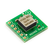 |
| ADXRS610 Gyro |
I wired it up, mounted it between two foam pads for further isolation, and performed the servo / motor experiment again. Here's the plot.

After that I ran the servo and the motor a few times. The truck vibrated around and changed its heading slightly. I pushed it back into place. You can see these subtle events on the plot.
What you can't see are the massive output swings like the LISY300AL exhibited. Cool! I think this sensor is a winner. High vibration rejection indeed!
Real World Driving Test
Next, I tested to see how it performed in a real driving test. The results were promising. Here's a plot of a subset of the data from an extended test run.

Verifying Heading With GPS
To find out, I compared gyro heading to GPS heading. I tweaked some Perl code to convert the raw gyro readings to heading and plotted that against GPS heading data from the test run.
I initialized the gyro heading to align initially to the gps values and then subtracted the fix age time from the gps heading readings to time align both plots.

You'll have to click the plot to see a larger image and make out the relevant detail.
Heading data from the gyro (red) is fairly smooth and it matches the general shape of the gps plot (green) which is great news, even if the scale and absolute heading are off.
This result suggests that the gyro readings may get quite a bit closer to the GPS readings by calibrating the gyro for temperature, null point and scale.
In the end, the noise issue was specific to the LISY300AL gyro and seems to be alleviated.
No comments:
Post a Comment
Note: Only a member of this blog may post a comment.