Friday, December 31, 2010

Connecting mbed to Wiimote IR Camera

Background

I got some very interesting and wonderful presents this Christmas (thanks Mom, Dad, and Father-in-Law!). So... what can you make with a microcontroller, a Wiimote, and a laser?  More on that another time, if I can pull it off. But here's how you can run a Wiimote IR camera with an mbed and track a laser dot (or other light sources) on your Windows, Mac, or Linux host.

mbed Microcontroller
Meanwhile, my parents very generously gave me an mbed microcontroller -- a powerful ARM Cortex M3 on a 40-dip board. Thanks Mom and Dad!! You can see it hooked up in its first, post-"hello world" experiment.


Wiimote
The Wiimote I planned to hack was purchased with a most generous gift card from my father in law (thanks, Mike!) Inside the Wiimote is an infrared camera that tracks infrared light point sources and reports their coordinates over I²C.

Credit

I'm following in the footsteps of great hackers, here. Here are the sources for the Wiimote IR Camera hacks:
Extracting the IR Camera

After disassembling the Wiimote, I desoldered the camera using solder braid with some extra flux paste. I soldered the camera's 8 thin leads onto a 2x4 pin header and soldered that onto a perfboard with 1x4 headers on either side so I could easily breadboard the thing.


Wiring the Camera to the mbed

Using the mbed, the interfacing is super simple.

The LPC1768 is a 3.3V device, eliminating all the voltage level translation hassle that the 5V Arduino owners had to endure.

And, since it's running at 96MHz, programmed one of the mbed's PWM signals to output an ~20MHz clock signal for the camera.  No crystal oscillator necessary.

The camera pinout is shown in the image below.


Here's a quick and dirty schematic. Note the pullup resistors on SCL, SDA, and RESET. In kako's and others' schematics, there's a 0.1uF capacitor between RESET and GND, probably to filter glitches.  So far I've gotten away with omitting the cap.

Wiimote to mbed wiring schematic. Click for large version.
Software

Microcontroller Software
I converted kako's source code to mbed C++ and added the ~20MHz clock signal on p21, and setup I2C communication on p9/p10.  The source code listing can be found here.

Here some sample output over the USB serial device while the camera tracks a laser. The camera tracks four light sources and provides x and y coordinates. The output from the microcontroller is a comma-separated list of x-y pairs: x1,y1,x2,y2,x3,y3,x4,y4

239,272,360,299,1023,1023,1023,1023
235,267,353,292,1023,1023,1023,1023
237,274,359,300,1023,1023,1023,1023
251,284,368,305,1023,1023,1023,1023
253,292,375,319,1023,1023,1023,1023
253,298,374,322,1023,1023,1023,1023
256,299,376,322,1023,1023,1023,1023
258,299,376,319,1023,1023,1023,1023
...

PC GUI Client Software
I wanted to visually display the camera's tracking data, so I wrote a Java Swing equivalent of the CC2's ATM 18 Project BlobTracker Front End software, since I couldn't get it to work. Well, the Java app works pretty well. Here is the source code for the Java app.


I mentioned the laser and used it here, but I have other plans.  I'm still working on it.  If I pull it off I'll be sure to post.

Happy New Year!

Sunday, December 26, 2010

Renaming an Applescript Xcode Project

To rename an Xcode AppleScript project, follow the steps below, based on my experience using Aleksandar Vacić's article. I needed to rename my serial communications AppleScript project. I simplified and clarified some of the steps in Aleksandar's article and made them specific to an AppleScript project.
  • Close the project in Xcode. 
  • Copy/rename the folder into new name
  • Open the new folder and rename the .applescript* and .xcodeproj files to the new name
  • Delete the build folder
  • Right click .xcodeproj and select Show package contents, which will reveal several files
  • Edit each of these files with a text editor (TextEdit, vi, Vim, Aquamacs, etc.) and replace all instances of the old name with the new name. In vi (or vim), type :.,$s/oldname/newname/g
  • Load the project file in Xcode, select  Clean all targets
  • Now build the project
_______
* You'll need to rename whatever your source code file is, like .sch as in Aleksandar's article.

Friday, December 17, 2010

SP0256-AL2 Speech With Arduino

Here's the Arduino version of a project to use the General Instruments (GI) SP0256-AL2 vintage speech synthesis chip to say "hello world". I'd previously shown how to do this with a Basic Stamp 2.


Here's what it sounds like saying, "hello world" 20101215_164333.mp3

How it works, in short, is that the GI chip must be given an 8-bit address corresponding to a vocalization.  It sends an audio signal on its digital out pin which is filtered and presented to an LM386 audio amplifier with a speaker connected.

The 8-bit address is presented to the SP0256 on pins A1-A8. The address is latched into the chip with the !ALD (Address LoaD) pin. The address represents a speech sound in the chip's internal ROM which corresponds to an English allophone (like CH, SS, LL, EH, EE, AH, ...).  The SBY (standby) pin goes low until the chip is done speaking the allophone just presented.

I used a breadboard Arduino with ATmega328P and wired the address lines to PORTC (Arduino digital pins 0..5) so that in software I could simply assign the allophone address all at once ala PORTC = address rather than a pin at a time.  I arbitrarily hooked up !ALD to PD6 (digital pin 10) and SBY to PB1 (digital pin 9).  Here's a schematic that shows the hookup.


There are many more details to hooking up the SP0256. Here's a link to the datasheet I scanned in.

SP0256-AL2.zip (5.2 MB download)

Astute readers may have noticed the IR ranger in the schematic. My current plan is to create a device that speaks random phrases whenever a Sharp infrared ranger detects the presence of an object (like a person walking by).

As for the code, it was a simple matter of porting the BS2 code to C for Arduino.  Here it is:

/* SP0256-AL2 Speech Chip
 * Control Code

 * Text: HELLO WORLD.
 * Phoneme: HH EH LL AX OW (PAUSE) WW ER1 LL PA2 DD1 (PAUSE)
 * Octal: 033 007 055 017 065 003 056 063 055 001 025 004
 * Dec: 27 7 45 15 53 3 46 51 45 1 21 4
 */

char data[64];

// PINOUT
//  SBY -> PB1 / Pin 9
// !ALD -> PD6 / Pin 10
// A6..A1 -> PD5..0 / Pin 0..5
#define SBY 9
#define ALD 10
#define LED 13

void setup()
{
  int i;
  
  // DON'T USE Serial Ports!!!

  // LOAD data  
  i = 0;
  data[i++]  = 27; //HH1
  data[i++]  = 7;  //EH
  data[i++]  = 45; //LL
  data[i++]  = 15; //AX
  data[i++]  = 53; //OW
  data[i++]  = 3;  //PA4
  data[i++]  = 46; //WW
  data[i++]  = 51; //ER1
  data[i++]  = 45; //LL
  data[i++]  = 1;  //PA2
  data[i++]  = 21; //DD1
  data[i++]  = 4;  //PA5  
  data[i++]  = 0;  //end

  // Could do: DDRD = 0b00011111;
  for (int p=0; p < 6; p++) {
    pinMode(p, OUTPUT);
  }
  pinMode(ALD, OUTPUT);
  pinMode(SBY, INPUT);
  pinMode(LED, OUTPUT); // LED
}

void loop() 
{
  int i;
  
  i = 0;
  digitalWrite(ALD, HIGH);    
  while (data[i] != 0) {
    // Set address
    PORTD = data[i];
    // Set !ADL=0 for 2usec to tell the chip to read
    digitalWrite(ALD, LOW);
    delayMicroseconds(2);
    digitalWrite(ALD, HIGH);
    i++;
    // Wait for SBY=1 (standby) to indicate chip is done speaking
    while (digitalRead(SBY) == 0);
  }
  delay(2000); // delay 2 sec between phrases
}

A little trivia / history: When I first became interested in building a robot, way back in the late 80's in the days of big hair, record players, stone knives and bear skins, Radio Shack stocked these chips on their parts shelves. I got one of the last before they sold out. I connected it to my Commodore 64 cartridge port and got the chip to say stuff. This was my first real robotics project. Whee!

Friday, December 10, 2010

Fan Motor Driver Circuit

At long last, let's revisit Pokey's fan motor driver circuit, redesign it, and get it working in real life. Previously, we modeled the original, flawed motor driver circuit in a series on SPICE.

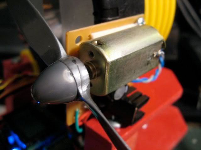
The fan is used on Pokey, my firefighting robot, to blow out the candle flame in a Trinity Robotic Firefighting competition. The motor and blade come from an entry level RC plane. I was running it off a common, everyday, 9V alkaline battery.

Since the fan only runs in one direction, a single transistor suffices to drive the fan, rather than an H-bridge. A simple circuit can interface the driver transistor to Pokey's ATmega MCU.

What not to do. 

One
The circuit's original incarnation featured a giant NPN transistor (15A!) with the motor between emitter and ground. That limits the current through the transistor, prevents it from saturating and, as a result, reduces the voltage and current available to the motor. It also heats up the transistor something terrible.

Don't do this.

The Fix. Instead, we want to place the load between Vcc and the collector, and tie the emitter to ground. If we're using an NPN, that is...

In this common emitter configuration, we can dump as much base current into the transistor as required to keep it in saturation, minimizing Vce so the motor receives maximum voltage and power, while the transistor stays cool.

Two
Next problem is in driving the 9V circuit with a 5V microcontroller. The ATmega MCU is limited to about 40mA output current. The circuit had to step up from 40mA to 1.8A.

In the second iteration, I swapped in a more appropriate ZTX649 NPN transistor (2A, continuous) as the driver. I decided to drive the power transistor with a small signal PNP, a 2N3906.

My "thinking" was that with the base of the PNP grounded through the MCU, the circuit would turn on fully (it did) and the MCU set high would be enough to turn off the transistor (it wasn't). The circuit never shut off.

This is why prototyping before etching a circuit board is a good idea. I would've saved myself some time and hassle. I have a beautiful little circuit board... for a circuit that is totally bogus.

Don't do this either.

The Fix. The PNP needed a pull-up resistor to force it off by default, using the MCU to ground the base and turn it on. Problem is, the MCU has to turn "on" the circuit by setting output low, and turn the circuit "off" by setting the output... not high, but to high impedance. That's messier than it needs to be.

Three
I discovered that 9V batteries are not very good at delivering high current. In fact they suck. But at least they have low energy capacity. Sheesh.

These limitations are undoubtedly because 9V batteries are comprised of many small battery cells. Each cell probably has some series resistance so when you draw a lot of current, the voltage drop in the battery gets very high (on the order of 2V in this particular application).

The Fix. As soon as I strapped an 1800mAH, 6-cell, NiMH RC car battery to the fan, I knew I was done with the little 9V.  The fan is plenty strong now. Just watch the vid below.

Also, with the high current battery, I discovered that the motor draws closer to 4A steady state, not 1.8A!

What to do.

Use a PNP to drive the motor.  This seems to me like the simplest way for a lower voltage input to control a higher voltage motor.

I did some more research in my old EE books, and on the web and came across an example circuit that uses a PNP power transistor driven by an NPN transistor to interface with the MCU for a simple, clean interface: set the motor pin high to turn on the motor, low to turn it off.

That combined with some experimentation and SPICE modeling and I put together a circuit that can drive 4A without any problem, using only a few mA of current from the MCU.

I selected a TIP42 PNP transistor from Radio Shack as the driver. It's capable of driving 10A, which is overkill here, but I had the transistor on hand and I was too impatient to search for and order anything else.

The PNP emitter connects to 9V, the collector to one side of the motor. Ground the other motor pin.


Tie the PNP base to the 9V source through a pull-up resistor to force the transistor off by default, Also connect the base to the collector of the interfacing NPN, using a resistor in series to limit base current in the PNP.

The interfacing NPN base is tied to the MCU through a current limiting resistor, but is also tied to ground through a pull-down resistor to ensure the circuit is off whether connected or not.

Now, about resistor values. Pull up and pull down resistors can be 10K.  Or probably more but that's high enough that they are effectively open when the motor is on and draw very little current with the motor off.

We start with the TIP42, Q1, which has hfe=20, minimum. To calculate Ibsat, the saturation current into the base, I've seen suggestions to divide Ic by 10. So, 400mA.

You can also calculate Ib right at the edge of saturation using Ic = hfe(Ib) and then multiply by an overdrive factor of 2-10.  Ib = 4.0A / 20 = 200mA. With overdrive factor, we get 400mA-2000mA drive current.

Even 400mA is too much for many small signal TO92 transistors and 2A certainly is too much! Remember the ZTX649 NPN from above? With a 2A continuous rating and a huge hfe=200, it was perfect to drive the TIP42. So we'll use that.

Calculate the ZTX649's saturation Ibsat = Icsat / hfe * 2  = 4mA.

Now, analyze the circuit using values for Vce (per datasheet) and/or Vbe (0.6V) and find the resistances.


Model!

I used LTSpice to model the circuit to make sure I was in the ballpark. The modeled values for saturation current seemed on par with the resistances selected. I tweaked the motor resistance until Ic = 4.0A.

Prototype, Prototype, Prototype

No more etching boards until I prototype first. I built the circuit on a Sparkfun mini breadboard, and tested Vcesat, Ib for the two transistors and also tested temperature on the transistors (with my finger) and all seems reasonably ok. I haven't yet prototyped the new values I calculated above, but I will before I etch the board.

Prototype, TIP42 top right, ZTX649, lower left.
Transistors are in saturation (cool, low Vce), motor spins with about as much speed as directly connected to the battery.  Which is to say, the motor spins really fast...


Only problem, the fan sometimes comes on partially when connecting motor power with the MCU off. Good thing I didn't etch the circuit yet...

Circuit and PCB Design

Despite this glitch, I wanted to fiddle with PCB design. I used Eagle once again to draft the circuit and build the board.

With some trial and error and some tweaking I was able to get everything to fit on a 1.000" x 0.875" board. Pretty tiny for through-hole!

I added power and motor on LED indicators to the circuit as well as a 100uF capacitor to handle the initial high current draw when the motor kicks on.

Circuit diagram (without power indicator LED)
PCB layout, power indicator added
All I needed was a small battery pack with enough current capacity.  So I borrowed a 6-cell, 2/3 A NiMH pack that a friend of mine used in his RC rock crawler.  It works quite well.

Here are the LTSpice and Eagle files for the circuit:

FanMotorDriverFiles.zip

Friday, December 3, 2010

LTspice Tips: Custom Components

So you've got LTspice, but you need to add a custom component, like a motor, or Op Amp or digital logic or something. Not just a simple transistor but some wildly complex black box type of thingy.

No problem. Here's how.

Overview

Whereas in MacSpice one has to manually set up files with subcircuits to be included for modeling complex devices, LTspice front ends these SPICE features by enabling the user to create new components. First, you draft a new symbol, in this case, I drew a typical motor symbol (right), a circle with an M in it, and two pins (ports) shown as squares.

Next you set up a schematic in the same directory and with the same base name as the symbol (e.g., motor.asy and motor.asc). You associate the pins/ports on the drawing with those in the schematic and now you can just plug in this component by adding it out of your directory just like you'd add any other LTspice component. This is a pretty clever approach that gives LTspice a lot of flexibility and power.

Behind the scenes, LTspice is using subckt cards to implement this hierarchy. It puts the subcircuit description inline in your circuit diagram when you load a component. You can see how this is implemented by selecting View > SPICE Netlist.

Walkthrough Example: Creating a Motor

Create a symbol. Select New Symbol from the File menu. Use the drawing tools in the Draw menu to create a circle with an M in the middle (schematic symbol for motor).


Circles are defined by clicking two points, upper left and lower right. You can use the drag tool to center it. Text is added with the text tool of course, and you would want to select centered justification.


Now it's time to add pins/ports. From the Edit menu, select Add Pin/Port (see image below left).  Label the ports "a" and "b". Then click the location on the symbol where the port belongs. I added a port at the top and bottom. Now, draw a line/wire from each port to the main body of the device--the circle in this case (see image below right).


Save the file under LTspiceInstallDirectory\lib\sym\YourSubDirectory as an .asy file, such as motor.asy


Create a Subcircuit. A subcircuit is the schematic that is inside the symbol's "black box". Open a new schematic and draw the components that model your motor.


Let's just simply model the motor as a resistor. So, add a 16 ohm resistor, call it RM. Now, add two wires on each end of the resistor. You can always make the model more complex later.


Label each wire to match each port in your symbol. In our case, label the wires (aka nets) "a" and "b". Save the file into the same directory as the symbol file and give it the same motor base name. So save the file as motor.asc


Use the Component. Now, open a new schematic, and add a component. Select the motor component that should now appear (if for some reason it doesn't, make sure you opened a new schematic after creating the symbol; if all else fails restart LTspice). Add it to your schematic.


Toss in a voltage source, set it to 9 VDC. Wire it up and add a ground.


Click the Run Simulation tool. Click the DC op pnt (operating point) analysis tab. Click ok. The simulation should run and you should see some current through the motor component.


Here's a zip file of the files I created for this walkthrough: ComponentDemo.zip

And that's all there is to it.

Thursday, November 25, 2010

Ideas for cheap Laser Rangfinder

The bounty for hacking the XV-11's $30 LIDAR, teardown talk on Sparkfun and hacking thread on Trossen Robotics prodded me into doing some quick experiments.

I've been pondering, but not actually doing anything with laser-based object detection for a year now, for both the Trinity-style firefighting competition and the Sparkfun AVC.

The XV-11 unit looks to me like a camera and a laser pointer spun by a small CD motor (details of the system in this white paper). Picture from Sparkfun below. How hard would it be to hack something like this together?


Awhile ago I bought a line-generating laser to identify obstacles. Powered with a LM317 generating the required 3.0V, the laser generates a pretty nice line once you focus it.


Based on ideas I found online, one places the laser at some point low on a robot, with the laser's axis and line parallel to the ground, while the camera is placed some distance above and pointed slightly down, so that parallax can be leveraged.

A horizontal line is generated lower in the camera image for nearby objects, and higher in the image for far away objects.

Since I'm using Pokey's grayscale camera, rather than a color camera, I took pictures with and without a photographic red filter to see if that would help distinguish the laser reflection.

Laser line, red filter. Note height of line on cup, laser printer.

Laser line, no red filter

One could probably write code to detect the line even in a grayscale image although this would be substantially easier with an IR laser and IR filter. Or with a color camera.

Here's a color picture of the test area, my desk. Old HP laser printer to the left, McD's cup, front and center, etc.

As for the LIDAR concept, put a camera next to a laser pointer, align them to leverage horizontal parallax so one can measure distance based on the position of the dot.

I was curious to see what a tiny red laser pointer dot would look like on the grayscale camera. The dot is pretty tiny at about 8' distance (see red arrows).

Distant dot (red arrow), no red filter

Distant dot, with red filter

Maybe too tiny to reliably detect, although with the LIDAR one can constrain the search area vertically and possibly horizontally.

And constrain the search algorithm to square and circular shapes.

Come to think of it the code could correlate dot size with position for added robustness.

And actually the red filter seems to make the laser dot the brightest thing in the image, once the exposure and gain is set properly.

Nearby dot, no red filter

Nearby dot with red filter
Once code and camera can find the dot, the system has to do it quickly so it can be mounted on something spinny.

Doing a 360 degree sweep at 10Hz like the XV-11 means 3600fps which suggests it is using a much faster optical device than Pokey's camera or anything like it. I am guessing Neato is using a linescan sensor. You also need a fast processor. Speculation on the Sparkfun teardown blog post points to a Texas Instruments DSP device, TMS320C2801 at the heart of the XV-11 LIDAR's image processing.

I hit a wall at 3fps with an Arduino running Pokey's camera. I'm in the middle of interfacing with a Propeller but at absolute best I can get from that camera is 30fps. Nowhere close to fast enough for LIDAR. But workable with the laser line sensor concept. But all that's best left to another blog post or two.

I plan to just wait for someone to hack the XV-11 LIDAR and wait for spare parts to come out of Neato and hope I can afford the darn thing or build it myself for $30 as promised.

Sunday, November 21, 2010

Robotics goodies on sale...

Check it out, microcontrollers and other robotics goodies on sale. No affiliation with either company. Hope this is helpful to others on a shoestring budget like me.

Pololu is doing a black Friday sale with great prices on what I think is really useful stuff. I'm a fan of Pololu; Pokey's brain and drivetrain came from them. Good guys. Anyway, I have my eye on the $20 Orangutan B-328, $10 dual serial motor controller, $5 step-up step-down regulator, and $9 3-axis accelerometer but there's a bunch of stuff others might want too.  Hm, I better check my bank account balance...

Newark's Element-14 has some nice promotional deals going on controller boards like a $17 Multicomp Arduino board (35 day lead time, though), Multicomp Mega for $35, a Multicomp Nano for $28, an Amicus18 PIC board for $32 and an NXP OM11042 rapid prototyping board for $41.25 with the NXP LPC2368 ARM7 MCU.

Friday, November 19, 2010

Sparkfun AVC 2011: RC Truck

I had some birthday money burning a hole in my pocket and I've been thinking about the Sparkfun Autonomous Vehicle Contest too much lately.

I bought an budget-friendly, entry-level 1:10 RC truck.  An ElectrixRC Circuit.


I guess I'm going to go ahead and do this AVC thing. There's a long to do list. Let's see here...
  • Interface Arduino MCU to RC truck (done)
  • Research truck's handling limits* (in progress)
  • Collect acceleration data (in progress)
  • Devise Electronic Stability Control algorithms
  • Setup Android coding environment
  • Ramp up on Android coding
  • Explore using Android phone for navigation
  • Arduino to Android interface (bluetooth?)
  • Devise curb & object detection mechanism -- vision? laser? lidar?
Since Sparkfun hasn't actually announced the 2011 contest yet, I'm not sure how much time I have left but I'll assume it's happening around tax time again.  In fact, there's no guarantee the AVC will happen at all but I'm hopeful based on a comment on their website by an employee:

Although we haven't made any official AVC 2011 announcement (and this isn't one either), everybody around the office is assuming that AVC will continue every year into the indefinite future. It's just too much fun not to do it! Trevor

What I've learned so far about using my phone is that it lacks gyros, kind of a big deal I fear.  It makes the interface with the Arduino a little messier than I'd prefer.

Pic from Sparkfun.com
The 1-axis gyros I ordered from Sparkfun arrived, so I will most likely let the Arduino handle IMU interfacing, and have the phone manage the high level GPS and compass navigation.

---
* Yes, of course I'm going to get to play with the truck! Duh!

Friday, November 12, 2010

Thompson Robotics Expo

Pokey has been on loan to George of SHARC who took the robot to the Thompson Robotics Expo in Loveland last weekend.

The expo featured two robotics competitions. Of the 60 teams from the Thompson School District in Loveland, 22 teams competed to go to the VEX World Championship in Orlando, Florida while another 38 teams competed in a FIRST Lego League qualifier.

The event also showcased exhibits from the Denver Museum of Nature and Science, a robot mannequin simulator from Banner Health, MATE underwater robots, a robotic dog from Road Narrows, an Antartica underwater robot simulator, a demonstration of Thompson Valley's and Loveland High's FIRST Robotics Challenge robots, BEST robotics competition demo, and of course the SHARC firefighting demo with several robots, including Pokey.

George sent me an email a few days before the expo. With the motivation of an event deadline I got busy, reassembled the robot and thrashed on the code to add a number of enhancements.

Though still without a working fan motor driver, and lacking any kind of maze navigation code (bluetooth remote control only) Pokey's working better than ever and I'm told he performed well for the kids. Cool.

Pokey navigating the upper right corner of the maze. (Pic by George Mitsuoka)

Monday, November 1, 2010

Android (Phone) Robot for Robomagellan

As of a couple weeks ago, I've entered the new millenium with the purchase of an Android phone, an LG Ally (pic from intomobile.com).

Though I'm notoriously a Mac guy and most of my friends expected me to get an iPhone, my blogs, pictures, email, calendar, etc., are all hosted on Google.

And I was drawn to it because it's programmable in Java. On the other hand, programming the iPhone... well, let's just say that Robotgrrl successfully scared the bejeepers out of me in one of her blog entries with such quotes as:

If you’re ever looking for a challenge worth pulling your teeth out, making an iPhone App is a great place to start. 

and

The language, the concepts, everything is completely different from what is seen in languages like Java and C++.

Um, no thanks. Not that I'm a Java master, or anything. I'm a newb (and how many people are truly masters with an API that big anyway?).  But at least I'd be facing a learning curve instead of a learning cliff equipped with pillboxes and landmines. So Android was the obvious choice all around.

I got to thinking, gee, this thing has a GPS, a compass, and a 3-axis accelerometer, all the stuff that would cost me a couple hundred bucks to add to a scratch-built robomagellan robot.

That is, if I were to follow my dream of entering the Sparkfun Autonomous Vehicle Contest in 2011. Or any other robomagellan-esque challenge at any time in the near future.

So instead of a scratch-built robomagellan robot, why not an Android brain with the navigation smarts coded in, sitting atop some cheap RC chassis equipped with an Arduino brain stem, and some simple comm code on both ends for control.

That has to be easier and better than trying to do all this with 8-bit, 16MHz microcontrollers and C, right? I'd say so. Did I mention that OpenCV has been ported to Android?

Here's a great PDF write-up on the topic of Androids for robotics and robomagellan.

Friday, October 29, 2010

Happy Halloween!

Pokey couldn't think of anything else to be for Halloween this year...

Happy Halloween from Pokey and Bot Thoughts!

Friday, October 22, 2010

Wheel Encoder Generator

Announcing the latest version of my Wheel Encoder Generator for MacOS, Linux, and Windows, updated for 2021.

Screenshot, binary encoder disc

Wheel Encoder Generator is application you use to print your own robot encoder discs, just like I did for my AVC-winning autonomous rover, Data Bus. I rewrote the application from the ground up in 2021 using JavaFX.

Download

GitHub Source Repository

Flexibility. The application will create incremental encoder discs (below) of any diameter with or without quadrature and index tracks; it'll also make absolute encoder discs (above) of any size using either binary or gray code.

Speed. It instantly displays a preview of your encoder disc as you make changes. The interface is streamlined to put all the configuration a few clicks and keystrokes away. Toolbar buttons and accelerator keys speed operation.

Convenience. The window and preview image are resizable so you can get a giant preview image if you want. The interface is simple and (I hope) intuitive.

Save Your Work. You can save, load and print encoder patterns. You can export them as images.

High Resolution. Encoder resolution is theoretically limited only by the dpi resolution of your printer but the code enforces some (arbitrary) limits: 4096-positions, 12 tracks, 0.088° resolution for absolute encoders and incremental encoders with 0.1° resolution.

Cross Platform. The app runs on Windows, MacOS, and Linux.

Friday, October 15, 2010

Comparator With Automatic Voltage Reference

I'm working on building a circuit to adapt the output of wheel encoder sensors to a microcontroller. The output of these IR reflectance sensors is a sine wave, with some issues. Here's the general problem:

Let's say you have a sine wave, and the amplitude varies over time, and the signal is modulated by a lower frequency sine wave.  (In my head I was thinking it was kind of like if the DC offset were varying over time but of course DC doesn't vary...)  The sine wave has to be converted to a pulse train with a voltage comparator. Just pick a reference voltage and anytime the signal is higher than the reference, the comparator output is +5V (ish) and if it's below then it's 0V (ish). You can use a simple voltage divider or a potentiometer to set the reference voltage like so.

Comparator with potentiometer voltage divider for Vref

Simply using a voltage divider as a voltage reference to trigger the comparator isn't good enough. At best, the pulse width will vary as the sine wave varies. That can cause some inaccuracy in measuring speed and distance.

At best, pulse width varies and so does accuracy
At worst, you might miss pulses entirely if you can't get the voltage reference set just right or if the DC offset varies too widely.

It's possible to miss pulses with a fixed reference voltage
Wouldn't it be nice if we could automatically remove the signal component and leave behind the modulation and use that for the comparator reference voltage? Well, we can, and it's not that hard.

All we have to do is use a low pass filter. We filter out the higher frequency output of the wheel encoder sensors, and retain the modulation signal.  Basically what we're trying to do is adjust Vref to be a value between the upper and lower peak of our signal.  We take care of amplitude modulation at the same time.  This same approach can be used to automatically detect the DC offset of a signal and use that as Vref.

A simple low pass filter is more than adequate and keeps parts count low on the 1"x1" printed circuit board I'm designing. Pick a resistor in series with the signal input, and place a capacitor in parallel, and feed the output to the reference pin of your comparator. Like this:

Auto Vref using low pass filter to detect DC offset/amplitude fluctuation
You can experiment in LTSpice or in real life with different values for R and C but the formula to find the cutoff frequency is given by:


A higher value of R and C means the circuit cutoff frequency decreases, approaching but never reaching 0 (DC). You can imagine that a giant capacitor and resistor would filter out most ripple and a tiny resistor and capacitor wouldn't.

I measured the encoder frequency at approximately 100-200Hz. The slope of the frequency response curve for this type of filter is somewhat shallow so there is a tradeoff between the amount of higher frequency attenuation and how quickly the circuit reacts to changing DC offsets.

Frequency response of filter with higher cutoff frequency; -30dB at 100Hz

This first picture (above) shows a higher cutoff frequency and so it is more sensitive to changing DC offsets, but doesn't attenuate the encoder signal as much (-30dB at 100Hz). Which really isn't that big of a deal, as long as there is some attenuation.

Lower cutoff frequency attenuates the signal at 100Hz by -50dB
The picture above shows a lower cutoff frequency and so there's greater attenuation of the higher frequency encoder signal (-50dB at 100Hz). But if the DC offset fluctuates too rapidly, this circuit won't keep up. Because it's attenuating lower frequencies more, too.

In my case, a value of R=10k and C=1uF is a nice happy medium for my particular situation. More compact, low value capacitors didn't attenuate enough and higher capacitance prevented the circuit from tracking DC offset properly.

In the first video below you can make out the larger encoder waveform and the attenuated waveform that makes Vref. Notice how it tracks nicely between the peaks of the signal.


The second video shows the comparator output versus the encoder signal. Notice that the pulse width of the output remains fairly stable despite the DC offset and amplitude fluctuations in the signal.


Some of you may have noticed the phase shift introduced by the filter. This has the added bonus of adding hysteresis to the circuit making it more immune to noise.  [EDITED 11/07/2010]