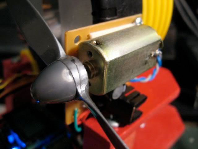
At long last, let's revisit Pokey's fan motor driver circuit, redesign it, and get it working in real life. Previously, we modeled the original, flawed motor driver circuit in a
series on SPICE.
The fan is used on Pokey, my firefighting robot, to blow out the candle flame in a
Trinity Robotic Firefighting competition. The motor and blade come from an entry level RC plane. I was running it off a common, everyday, 9V alkaline battery.
Since the fan only runs in one direction, a single transistor suffices to drive the fan, rather than an H-bridge. A simple circuit can interface the driver transistor to Pokey's ATmega MCU.
What not to do.
One
The circuit's original incarnation featured a giant NPN transistor (15A!) with the motor between emitter and ground. That limits the current through the transistor, prevents it from saturating and, as a result, reduces the voltage and current available to the motor. It also heats up the transistor something terrible.
 |
| Don't do this. |
The Fix. Instead, we want to place the load between Vcc and the collector, and tie the emitter to ground. If we're using an NPN, that is...
In this common emitter configuration, we can dump as much base current into the transistor as required to keep it in saturation, minimizing Vce so the motor receives maximum voltage and power, while the transistor stays cool.
Two
Next problem is in driving the 9V circuit with a 5V microcontroller. The ATmega MCU is limited to about 40mA output current. The circuit had to step up from 40mA to 1.8A.
In the second iteration, I swapped in a more appropriate ZTX649 NPN transistor (2A, continuous) as the driver. I decided to drive the power transistor with a small signal PNP, a 2N3906.
My "thinking" was that with the base of the PNP grounded through the MCU, the circuit would turn on fully (it did) and the MCU set high would be enough to turn off the transistor (it wasn't). The circuit never shut off.
This is why prototyping before etching a circuit board is a good idea. I would've saved myself some time and hassle. I have a beautiful little circuit board... for a circuit that is totally bogus.
Don't do this either.
The Fix. The PNP needed a pull-up resistor to force it off by default, using the MCU to ground the base and turn it on. Problem is, the MCU has to turn "on" the circuit by setting output low, and turn the circuit "off" by setting the output... not high, but to
high impedance. That's messier than it needs to be.
Three
I discovered that 9V batteries are not very good at delivering high current. In fact they suck. But at least they have low energy capacity. Sheesh.
These limitations are undoubtedly because 9V batteries are comprised of many small battery cells. Each cell probably has some series resistance so when you draw a lot of current, the voltage drop in the battery gets very high (on the order of 2V in this particular application).
The Fix. As soon as I strapped an 1800mAH, 6-cell, NiMH RC car battery to the fan, I knew I was done with the little 9V. The fan is plenty strong now. Just watch the vid below.
Also, with the high current battery, I discovered that the motor draws closer to 4A steady state, not 1.8A!
What to do.
Use a PNP to drive the motor. This seems to me like the simplest way for a lower voltage input to control a higher voltage motor.
I did some more research in my old EE books, and on the web and came across an example circuit that uses a PNP power transistor driven by an NPN transistor to interface with the MCU for a simple, clean interface: set the motor pin high to turn on the motor, low to turn it off.
That combined with some experimentation and SPICE modeling and I put together a circuit that can drive 4A without any problem, using only a few mA of current from the MCU.
I selected a
TIP42 PNP transistor from Radio Shack as the driver. It's capable of driving 10A, which is overkill here, but I had the transistor on hand and I was too impatient to search for and order anything else.
The PNP emitter connects to 9V, the collector to one side of the motor. Ground the other motor pin.
Tie the PNP base to the 9V source through a pull-up resistor to force the transistor off by default, Also connect the base to the collector of the interfacing NPN, using a resistor in series to limit base current in the PNP.
The interfacing NPN base is tied to the MCU through a current limiting resistor, but is also tied to ground through a pull-down resistor to ensure the circuit is off whether connected or not.
Now, about resistor values. Pull up and pull down resistors can be 10K. Or probably more but that's high enough that they are effectively open when the motor is on and draw very little current with the motor off.
We start with the TIP42, Q1, which has h
fe=20, minimum. To calculate I
bsat, the saturation current into the base, I've seen suggestions to divide Ic by 10. So, 400mA.
You can also calculate Ib right at the edge of saturation using Ic = h
fe(Ib) and then multiply by an overdrive factor of 2-10. Ib = 4.0A / 20 = 200mA. With overdrive factor, we get 400mA-2000mA drive current.
Even 400mA is too much for many small signal TO92 transistors and 2A certainly is too much! Remember the
ZTX649 NPN from above? With a 2A continuous rating and a huge h
fe=200, it was perfect to drive the TIP42. So we'll use that.
Calculate the ZTX649's saturation Ibsat = Icsat / hfe * 2 = 4mA.
Now, analyze the circuit using values for Vce (per datasheet) and/or Vbe (0.6V) and find the resistances.
Model!
I used LTSpice to model the circuit to make sure I was in the ballpark. The modeled values for saturation current seemed on par with the resistances selected. I tweaked the motor resistance until Ic = 4.0A.
Prototype, Prototype, Prototype
No more etching boards until I prototype first. I built the circuit on a
Sparkfun mini breadboard, and tested Vcesat, Ib for the two transistors and also tested temperature on the transistors (with my finger) and all seems reasonably ok. I haven't yet prototyped the new values I calculated above, but I will before I etch the board.
 |
| Prototype, TIP42 top right, ZTX649, lower left. |
Transistors are in saturation (cool, low Vce), motor spins with about as much speed as directly connected to the battery. Which is to say, the motor spins really fast...
Only problem, the fan sometimes comes on partially when connecting motor power with the MCU off. Good thing I didn't etch the circuit yet...
Circuit and PCB Design
Despite this glitch, I wanted to fiddle with PCB design. I used Eagle once again to draft the circuit and build the board.
With some trial and error and some tweaking I was able to get everything to fit on a 1.000" x 0.875" board. Pretty tiny for through-hole!
I added power and motor on LED indicators to the circuit as well as a 100uF capacitor to handle the initial high current draw when the motor kicks on.
 |
| Circuit diagram (without power indicator LED) |
 |
| PCB layout, power indicator added |
All I needed was a small battery pack with enough current capacity. So I borrowed a 6-cell, 2/3 A NiMH pack that a friend of mine used in his RC rock crawler. It works quite well.
Here are the LTSpice and Eagle files for the circuit:
FanMotorDriverFiles.zip