Friday, September 24, 2010

Core War!

Two programs enter. One leaves. Picture this, tiny assembly language programs battling each other in core memory space* each trying to overwrite the other. Survival of the fittest.

Programs attack!
It's called Corewar. It's a game. A really cool, but kind of old programming game. I haven't looked at it in years but something made me think of it.

The appeal for me is the opportunity to think really creatively about assembly coding. It seems like good mental exercise. Maybe it will jar me into some epiphany about my vision code so I can get more than 3fps frame rate...

The game's assembly language, called Redcode, has 17 instructions and programs run on a virtual computer, the Memory Array Redcode Simulator (MARS) consisting of 8000 memory locations*. You can download various MARS implementations like A.R.E.S. or pMARS.
The goal is to try to get another program to execute a DAT opcode, which will crash it. To do this, your code (warrior) has to drop a DAT into memory right where the other warrior's Program Counter (PC) is pointing to run the next instruction.

Here's sample code from Corewars for Dummies.
;redcode-94
;name Sleepy
;author John Q. Smith
;strategy bombing core

ADD #10, #-1
MOV 2, @-1
JMP -2, 0
DAT #33, #33

end
The instruction ADD #10, #-1 is a self-modifying instruction. It adds the constant 10 (# specifies immediate addressing) to the constant in the second argument. When done the instruction becomes ADD #10, #9

The instruction MOV   2,  @-1 attempts to move the data in the memory cell PC+2 (the line DAT #33, #33) to the location specified in the second argument of the previous instruction... #9, that is. So it attempts to copy DAT #33, #33 to a location in memory 9 cells beyond the current program counter. Or, PC+9.

You can imagine JMP -2, 0 jumps back to the ADD line. That is, it sets PC = PC-2. And the process starts over. Basically the code drops DAT bombs every 10 memory cells.

Here's what battling warriors look like. Dig the cool 8-bit game music.


---
* von Neumann architecture, of course.

Wednesday, September 22, 2010

PryoElectro.com: Mini-Tank Line Follower

All analog, mini-tank, line-following robot
Chris over at PyroElectro.com sent along a link to his write-up for building a mini-tank line follower robot.

I thought I'd pass it along for those itching for a fun DIY robotics project to work on. If you've never built a robot before this could be your first!

It's based on a Tamiya tank kit, gearbox, and basic discrete analog components to follow a line. The write-up includes parts list, circuit diagrams, and very detailed instructions for constructing the robot. Nice!

Also included is a movie of the robot in action. It looks like it works really well. Nicely done, Chris!


This PyroElectro.com site has all kinds of interesting projects from guitar tube amps to turning your oscilloscope into a TV to various robotics projects. Definitely sub'ing to the RSS feed.

Friday, September 17, 2010

Arduino / AVR Analog Comparator

As you may recall, I was working on detecting a candle flame using a Game Boy camera interfaced to an ATmega328P (in the form of a Solarbotics Ardweeny) coded in the Arduino IDE.

The AVR's onboard analog-to-digital converter is very slow. Too slow even for very low resolution (128x123) image capture. Frame rate was around 0.25 - 0.5 fps (that's one frame every 2-4 seconds).

Instead of adding an external ADC (I'll try that later), the simplest option for speeding up the frame rate was to use the MCU's built in analog comparator. Since the system only had to detect a bright spot, an 8-bit greyscale capture was unnecessary.

The AVR comparator sets one of the register bits high if the input voltage (typically the AIN1 pin) exceeds the reference voltage (the AIN0 pin) and sets it low if not.

Doing so takes a measly 1-2 clock cycles. At 16MHz that's 0.125 µsec, which is several orders of magnitude faster than the ADC.  For example, using the Arduino analogRead() function takes 100 µsec.  To maximize the frame rate there was a few more tricks to implement.  But first...

AVR Analog Comparator

Here's how to use the basic features of the AVR analog comparator. The AVR has two pins, AIN0, the positive input for the comparator and AIN1, the negative input. Optionally you can use any of the other ADC pins for the negative input, but let's focus on the simple solution, using AIN1.

To set things up (don't panic, code will follow shortly)...
  • Set up the AIN0 (PD6) and AIN1 (PD7) pins for input
  • Enable the ADC -- and/or set ADEN (ADC enable) in the ADCSRA register
  • Enable the comparator -- clear ACD (analog comparator disable) in the ACSR (analog comparator control and status register)
  • Disable the comparator multiplexer -- clear ACME (analog comparator multiplex enable) in the ADCSRB register.
  • Disable interrupts for the analog comparator -- clear ACIE in the ACSR.
The simple answer is to set all three registers' bits to 0 except set ADEN which I presume allows you to continue to use the ADC normally if needed.  Here's the C code:

  // Initialize Comparator - obviously this is done differently for AVR
  pinMode(6, INPUT);
  pinMode(7, INPUT);

  // ACD=0, ACBG=0, ACO=0 ACI=0 ACIE=0 ACIC=0 ACIS1, ACIS0
  // - interrupt on output toggle
  ACSR = 0b00000000;
  // ADEN=1
  ADCSRA = 0b10000000;
  // ACME=0 (on) ADEN=0 MUX = b000 for use of AIN1
  ADCSRB = 0b00000000;


Using the comparator substantially increased frame rate... to about 1 fps. But it was still a little too slow, primarily because of the object detection being performed on the AVR.

The Final Tricks

A high frame rate, or even 10fps would've been nice to achieve. But for purposes of aiming the firefighting robot at a candle, a sad 3 fps was acceptable.

Getting to that level of "performance" involved code tuning, which consisted of reducing and optimizing the machine code between the clock pulses sent to the camera, and reducing the size of the code as much as possible, and finally eliminating parts of the code.

Simple Machine Code Optimization
My simple process for optimizing machine code of compiled Arduino source is as follows:
  • Compile within the Arduino IDE, 
  • Generating an assembly file from the command line (Cygwin in this case
  • Count instructions and look at data references. 
  • Change code to try and reduce instructions
  • Change the way data is referenced (e.g., several arrays or array of struct; copy point to local variable)
  • Repeat process to see if changes reduced the instruction count

Nothing sophisticated, mind you. Just a question of trying different ways to reference data structures and write code that reduced assembly instructions.  This helped a little.

To do it, you'll need to run the avr-objdump command on the elf file generated by the Arduino IDE compiler. The elf file can be found in the applet subdirectory of your project.  The command to run is:

avr-objdump -S project.cpp.elf > project.S

You can then edit the .S (assembly) file to count instructions. Source code appears as comments in the assembly file to make it easier to locate relevant code.  For example:

// Continue reading the rest of the pixels and flood fill to detect bright objects
// The camera seems to be spitting out 128x128 even though the final 5 rows are junk

  for (y = 0; y < 123; y++) {

    if (y < 16)
     972:       10 31           cpi     r17, 0x10       ; 16
     974:       10 f4           brcc    .+4             ; 0x97a <__stack+0x7b>
      sbi(CAM_LED_PORT, CAM_LED_BIT);
     976:       5d 9a           sbi     0x0b, 5 ; 11
     978:       01 c0           rjmp    .+2             ; 0x97c <__stack+0x7d>
    else
      cbi(CAM_LED_PORT, CAM_LED_BIT);
     97a:       5d 98           cbi     0x0b, 5 ; 11
     97c:       24 2f           mov     r18, r20
     97e:       50 e0           ldi     r21, 0x00       ; 0
     980:       71 e0           ldi     r23, 0x01       ; 1


The big difference came when I eliminated the part of the object detection code that attempted to merge nearby objects on the fly during capture. That work is now done after the image is captured and object coordinates are generated. The approach worked reliably and improved frame rate considerably.

Conclusion

I felt I hit a wall in speeding up the code and put it on the back burner for awhile.  Working up to a 5 or even 10 fps frame rate with an AVR seems like a daunting task.  Let alone the 20-30fps some robotic camera systems can achieve.

I am contemplating a processor upgrade, instead of more attempts at optimization. I recently purchased a Parallax Propeller to play with. Another possibility is an inexpensive ARM processor I ran across.

I would like to try using the camera for robust object detection and avoidance and that, most likely, will require greyscale capture.  I have a few fast ADCs to experiment with if the ARM or Propeller can't hack it.  Even without greyscale, vision-based object avoidance will need a much higher frame rate.

Tuesday, September 7, 2010

Texas Instruments MSP430 LaunchPad

The MSP430 Launch Pad arrived! Christmas came early!
Look what just arrived in the mail!  It's the ultra low-cost Texas Instruments LaunchPad, a USB-based experimenter board I ordered a few weeks ago. The board is for experimenting with 14/20-pin MSP430 Value Line microcontrollers, designed for low power consumption as well as low cost.

At only $4.30 the experimenter board is about as budget-friendly as you can get. The MSP430G2231 chips cost about $1.75 at Mouser, although two came with the box.

Development environment and tools are free at www.ti.com/launchpadwiki (Windows only). There's also a GCC toolchain, MSPGCC. Mac OS X folks, check this wiki page.

What comes in the box?  Experimenter board of course. USB cable. Pin headers, two MSP430G22231 14-pin PDIP MCUs, 32.768 kHz SMT cyrstal, and a couple of cute little LaunchPad stickers.

The MCU specs are: clock speed up to 16MHz, RISC architecture, 2kB Flash, 128B RAM, 10 GPIO, 1x 16-bit timer, USI (I2C, SPI), Internal Temp Sensor, and 8ch 10-bit ADC.

Contents. More goodies under the white tab.
Getting Started With LaunchPad, The Simple Way

  • I started by installing the IAR Embedded Workbench IDE for MSP430. The CCS tool requires at least 1G of memory and my garage sale PC is memory-challenged.
  • Next, open up the User's Guide for the IAR Embedded Workbench.
  • Read the Get Started Now! section which describes how to configure the IDE, compile, download and run your code.
  • You should have a flashing red LED on your LaunchPad. Yippee!

Now, let's see... what can we do with this thing?

The www.43oh.com website has lots of ideas. So do these sites: www.msp430launchpad.com and mspsci.blogspot.com  And there's the forum at 43oh as well as this Ti MSP430 Forum and this Google group and a Yahoo Group.

Friday, September 3, 2010

Eagle Tips: Pour Regions

I draft all my circuits and board designs using Eagle from CadSoft. I've now drawn dozens of circuits and created several PCBs using this software. I picked up some tricks along the way.

Today's trick is: using ground pour polygons to simplify PCB routing

When designing PCBs, I find it easiest to hand route most of my designs to ensure the traces are exactly where I want them.

One way to simplify the routing task is to use a ground pour, or polygons, in Eagle. Basically what this means is filling in all the blank spots on the PCB with copper, and tying all the ground pins to this swath of copper.

Using a ground pour region also saves you time and etchant if you're doing your own PCBs at home, because there's less copper to remove.

Here's how.

Walk Through Example

I created a PCB, below, to interface Pokey with serial adapters; a BlueSMiRF Bluetooth modem and a Sparkfun FTDI serial to usb adapter.

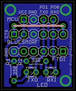
Serial adapter with ground pour region
Notice that there are large regions of the board colored blue, just like the other bottom traces. These regions are all part of the ground pour.

Let's rewind the clock and look at the serial board prior to laying it out.  It looks like this. The components aren't yet placed on the board, outlined in white. No traces exist, only thin yellow lines representing the ratsnest.
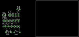
Components not yet laid out on the board to the right
Before you do anything else, create a polygon surrounding the board. Select the polygon tool (below left), draw a box around the outline of the board (below right). Make sure you're drawing the polygon on the Bottom (blue) layer.


Then right click the polygon outline, select Name from the contextual menu, and rename the polygon to GND which will connect it with the ground network in Eagle.

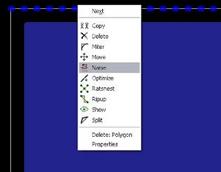
Right click the polygon, select Name
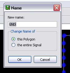
Enter GND as the polgyon's name
After you've created your ground pour, you can now move your components into place. If you click the ratsnest icon, the pour region will fill in and will connect any pin on the GND network to this pour region.

After clicking ratsnest, notice ground pins are connected.
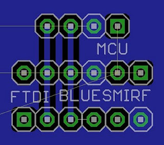
Isolate Pour and Traces

When doing my own PCBs at home, I find it helpful to put some space between the pour region and the traces. This is done with the Isolate parameter of the polygon. At home I find trace widths of about 0.024" to 0.032" are reasonable so this is the isolation setting I use.

Without isolation between pour and traces
Select the polygon, select properties, and choose 0.024" in the Isolation drop down menu.

With 0.024" isolation between traces and pour

NOTE: if a fabrication company is making your PCB, you may not be able to set isolation between the pour and the traces. Check with the vendor.

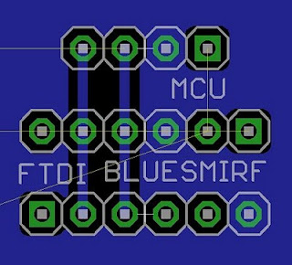
Use Orphans to Reduce Blank Spots

Sometimes there will be blank spots on the PCB that aren't contiguous with the ground pour, as in the example picture above. To minimize the blank areas on the board for home etching, you can have the ground pour create orphans, or islands of pour unconnected with anything else.

Kenneth, one of our readers, suggests we keep in mind that ungrounded blobs of copper can cause problems for high frequency signals. For home etching and low frequency it should be ok.

Select the polygon, select properties, and click the Orhpans checkbox. The default setting turns Orphans off.

Orphans enabled; note fill in between the two traces

Use Thermals for Easy Soldering

Thermal traces
I've found it much easier to solder pins to the ground pour region when Thermals are used.

Instead of connecting the pin to a huge chunk of copper, which acts as a heat sink, and makes for blobby, cruddy solder joints, up to four thin traces connect the pin's pad to the larger region. The traces are easier to solder, I've found.

Select the polygon, select properties, and click the Thermals checkbox. This is the default.

Use Top Layer To Connect Grounds

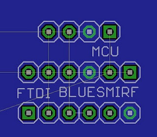
Sometimes two ground pour regions are separated by a single trace, leaving the two regions disconnected. When you're etching single layer boards, you can still use top layer traces, implemented with wires, to fix the problem.

In the example below the vertical trace on the left that is marked by a white line is preventing the ground pour region from being contiguous. The unrouted line shows that the Ardweeny and bottom pin header ground aren't connected electrically.

The ground pour region is split. See the unrouted line?
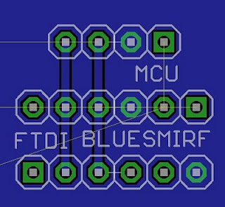
You can convert part of a trace to reside on the top layer allowing the ground pour region to 'flow' underneath the jumper and connect the two regions.

Below, the vertical trace is converted to a top layer. The ground pour is now contiguous.

The left vertical jumper fixes the ground pour split

If your board will be two layer, no problem. If it's a one-layer board just use hookup or bus wire to implement the top layer.