 Introduction
 Because I recover electrolytic capacitors from junked electronics for hobby use, and because I restore vintage audio equipment with old electrolytics, I wanted a way to test these capacitors as they are known to have a short lifespan compared to other components.
Bad capacitors, if they aren't shorted outright, will show a high equivalent series resistance (ESR) so I wanted to measure ESR by building Stephen M. Powell's ESR test harness.
I figure this meter will save me money by letting me salvage caps and replacing only those that have started to go bad.
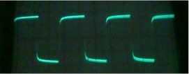
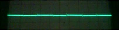
One can measure ESR of a capacitor by sending a small, high frequency square wave through it and looking at the wave form on an oscilloscope. Mr. Powell's circuit does just that, so I thought I'd share my build experience.
The Circuit
The circuit consists of two parts. On the left is the signal generator built around the good old 555 chip, designed to deliver a milli-Volt 100kHz square wave. It's design to be adjustable by way of the two variable resistors which control frequency and duty cycle as described on this handy 555 calculator webpage.
 The right side is the test harness which simply drops the peak voltage seen by the capacitor and oscilloscope. The back to back diodes bleed off any DC charge on the capacitor to avoid overvoltage reaching the scope or 555 IC.
Prototype
I prototyped a very simple version of the circuit on a breadboard and tested a few of my recovered capacitors (below middle). I did find a shorted capacitor (lower left), interestingly enough. I also saw the effect of a small capacitor integrating the square wave, resulting in a sawtooth wave (lower right).

Board Layout and Enclosure
 Laying out the board without knowing where the board will be install is kind of a time waster. Eventually I may learn this lesson and, next time ...
- Rough out the layout enough to get a sense of the board dimensions,
- Select the battery source to add to the required enclosure dimensions, and
- Find an appropriate box that can fit the board and battery.
 The datasheet for the enclosure shows the board dimensions and mounting hole placement and with a little massaging the board layout was done.
From the function generator project, I learned to leave room inside the box for switches hanging down from the top of the case.
So I left a large section at the front of the enclosure unpopulated by components so I could mount the on/off toggle and an toggle to select testing of high or low ESR caps at the front top of the case. The BNC connector and the capacitor probes will exit the front panel of the box.
Then I thought it might be helpful to see if I could render the board in 3d and ran across Eagle 3d, an Eagle ULP script, which generates a POV-Ray file, pictured at the beginning of the article.
Installation was easy for both Eagle 3d as well as POV-Ray. To get the rendering to work I had to copy the include files (etc) out of the Eagle 3d's Eagle\ulp\Eagle3D\povray directory into the My Documents\POV-ray\v3.6\includes directory so POV-ray could properly include the files. It probably wouldn't hurt to copy the Eagle 3d ulp script into Eagle's ulp directory.
Rendering only took a few seconds even on this old 1GHz P4 machine.
Parts Purchase
Lately I've found it is a giant pain in the butt to buy components for these projects, especially the oddball ones. While I have a stash of most of the components required for this project, a few things need purchasing. I thought I'd play around with the Bill Of Materials script in Eagle. Simply run the bom.ulp script and follow the dialog prompts to save a txt file.
I imported this file into OpenOffice Calc using fixed width separation and added a left column to indicate the items I needed to buy: a couple of switches that will fit in the 17mm vertical space between the top of the board on the bottom of the enclosure, the enclosure itself, some power resistors, and probe wires (possibly also banana jacks if I use removable probe wires, and a trim potentiometer in a size I don't have.
Next: Part 2