Friday, September 25, 2009

IR Repeater: Part 1

Introduction

Our Tivo, satellite receiver, and DVD player are on a shelf at the front of the living room, partially obscured by a sofa making it difficult to control them with remotes. I could go and buy an infrared (IR) remote extender (aka IR repeater), but what fun is that when I could build one? Plus, I want to use IR signaling for robotic communications so here's a perfect learning opportunity.


Requirements: The repeater will have to allow for very reliable control of these three devices, it should be aesthetically pleasing or at least unobtrusive, fairly small, and run for months off a pair of AA batteries.

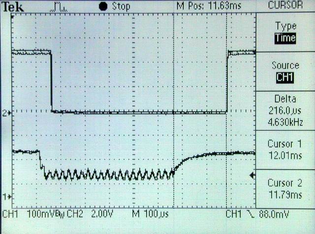
How Infrared Remote Works

The oscilloscope trace at the right shows the digital signal from the remote. There are multiple coding schemes for remote control like pulse, space, and phase encoding.

Some systems represent binary data in long and short pulses, or pulse coding. Others represent binary data as long and short spaces between fixed length pulses, or space coding. Phase coding represents data by way of signal transitions. The beauty of this IR repeater is that it doesn't really care what coding scheme is used; it simply passes the signal along*.

To avoid interference with ambient light, IR remote controls modulate the light signal at somewhere in the vicinity of 38kHz. That way the receiver isn't fooled into thinking some random flash of light is coming from the remote.

So we need a way to detect pulsed 38kHz IR light and convert that into logic pulses then repeat the signal as pulses of 38kHz modulated infrared light. Detecting IR remote signals and converting them to logic signals is exactly what IR detection modules are for, like the Vishay TSOP32138. An astable multivibrator and an infrared LED handle the rebroadcast.

The Circuit

After searching the web, I settled on a circuit from this website as a starting point. After some tweaking and experimenting I arrived at this:

The circuit, as you can imagine, breaks down into three sections, the receiver, the transmitter and, not pictured above, the power supply.

The receiver consists of an IR receiver module with an active low signal. This signal is inverted by a simple small signal BJT (bipolar junction transistor) as an input signal to trigger the transmitter.

The transmitter section consists of, no surprise, an IR LED, which is driven by another transistor. The LED is pulsed on and off at approximately 40kHz by a pulse generator circuit with a 555 timer IC at its heart. I'll fine tune the modulation in the near future.

The power supply will eventually consist of 2 AA batteries, for their compact size and energy density, and a voltage regulator to provide 5V to the parts that need it. For now I am using a 9V battery and a good old-fashioned 7805 linear regulator. I'll address power reduction in a later article.

The good news is the prototype circuit (see pic at the beginning of this post) works pretty well with our DVD player and satellite receiver. But we also have a TiVo and the TiVo is not happy.

TiVo Problems
When in operation, the repeater renders the TiVo remote utterly non-functional. I found an explanation at this website by Edwin Olson.

*Apparently the IR module is distorting the signal, so it isn't truly repeating the signal verbatim as I had originally hoped. After dragging out my trusty, massive Hitachi V1050F oscilloscope and after fiddling with knobs awhile, I finally duplicated Mr. Olson's results.
You can clearly see that the module is adding extra delay on the falling edge of the signal and virtually none on the rising edge. Hm, well, this is a bit of a problem. Stay tuned to see how I end up solving it. I can't wait to find out! :)

Thursday, September 17, 2009

Oscilloscope Calibrator: Part 3

Power Supply

The last item on the list for the oscilloscope calibrator is an AC to DC power supply. I couldn't really design that earlier because I wasn't sure what supply voltage and current would be needed for the amplitude amplifier. Now I do.

With the design settled on a 12VDC supply, and with some SPICE modeling, the supply needs to deliver at least 20mA. Meanwhile, a 5VDC, 0.5A supply should be enough to drive the TTL ICs.

To get regulated DC power, we need to convert line AC voltages to lower AC voltages, rectify AC signal, filter the ripple, and feed it to voltage regulator ICs.

Converting AC to AC

The first step is to convert a 115V, 60Hz AC signal into a much lower AC signal, 12VAC in this case, since 12V transformers are very easy to source like this 450mA one from Radio Shackicon for just over $6. I may upgrade to a higher capacity transformer in the near future to ensure the entire power supply can safely deliver more than enough current.

Converting AC to DC

Time to convert the 12VAC signal to DC. Before we can do that, we have to rectify the signal, that is, convert the negative voltage swings of the AC signal to positive swings. Typical rectifier diodes are 1N4001 thru 1N4007, each with a progressively higher voltage rating. Pick a voltage rating that is at least 2.83 x Vrms (in our case 12 x 2.83 = 34V). Hook up the diodes into a bridge rectifier topology. Or, use a bridge rectifier IC.

The output from the rectifier is not DC yet. The waveform's ripple needs to be filtered using large electrolytic capacitors. Select capacitance based on the desired ripple factor or just use the rule of thumb of 1000 to 2000µF per amp.

Choose capacitor working voltage with a safety margin above the peak to peak voltage of the rectified waveform. Multiplying the RMS (root mean squared) VAC by 1.414. In our case, 12VAC (RMS) has 16.968V peaks. I chose 35WVDC.

So now we have a nearly pure DC signal. It's good enough for the rectifiers (whose data sheets may tell you what ripple factor you need to engineer for).

Regulating DC

We'll now use a voltage regulator to smooth out the DC and fix it fairly precisely at the desired voltage despite varying load. Linear regulators are very popular and simple to use and come in several voltages, including 5V and 12V. The LM7805 does 5V and LM7812 does 12V. We'll use each for this power supply.

Linear regulators need a DC signal that is about 3x higher than the desired output voltage. The voltage difference is burned up as heat by the regulator. So if there's a big difference between the input voltage and output voltage (like 16V to 5V) a heat sink is required or we need to supply a lower voltage level to the regulator. I may end up selecting a separate 6VAC transformer.

Another capacitor can be added across the regulator output to ground to provide reserve current for increased demands. Usually something like 100uF/amp is suggested. When the circuit is turned off, the charge in this capacitor will dump back into the voltage regulator. To prevent this, a rectifier diode is placed to bypass this current from the output to the input terminals.

Lastly, small capacitors, 0.1µF to 1µF are placed close to the regulator body across input and ground and between output and ground, to reject noise.

Switch and Additional Protection

Use a polarized plug. This is the standard for most modern electronics to avoid shocks. To turn the power supply on and off, put a switch on the hot wire going to the primary windings of the transformer. Place a fuse inline on the hot side, between the plug and the switch. Pick a fuse that is about 2X the normal current requirement. Use a slow blow fuse.

Finding out the max current on the primary side is a question of finding the ratio of voltages (120/12 = 10 in my case) and then using that to figure out the current requirement. With two 2A regulators, the primary will see 200mA; 2 x is 400mA so the next closest size is 0.5A. If I find that inrush current that charges the large capacitor causes the fuse to blow, I can always size it up a bit.

Finally for surge protection, a Metal Oxide Varistor (MOV) is placed in parallel between hot and neutral, after the switch. Select one with a maximum continuous voltage of 20% more than the normal line voltage (for 115V, a 135V rating would work).

So here's the finished schematic. I have to build this circuit before I can test the amplitude section, because I don't have any other 12V supplies available.

I decided to try my hand at PCB fabrication for this portion of the project. Here's a picture of the rectifier / regulator board. It's almost completed. The transformer, MOV, fuse, and power connector are going to be external to this board.


Part 1: Signal Generator
Part 2: Amplitude

Part 4: coming soon


Sources:

Thursday, September 10, 2009

Simple DIY PCB Drilling

The next step in DIY printed circuit board (pcb) fabrication after designing the pcb layout and etching the PCB is drilling the holes. Drilling holes was much easier than I anticipated, probably because I chose the right tools.

PCB Drilling Tools

I needed mini carbide drill bits and a Dremel drill press / workstation or one like it (recommended by one online forum for DIY PCB fabrication).

The cheapest source I found for drill bits was this 50 piece grab bag from Harbor Freight, which took forever to arrive. Still, it contained a number of useful sizes for PCB drilling. The commonly used sizes appear to range from: #71 (0.026" / 0.66 mm) through #56 (0.0465" / 1.18 mm). They work beautifully.

I already had a Craftsman rotary tool and chose the matching Craftsman drill press for $40. Some suggest these hobby drill presses have too much side to side slop and will break drill bits. After drilling hundreds of holes in dozens of boards, I disagree. I believe the mechanism is tight enough and easy enough to use for PCB drilling.

In the picture below, you can see the rotary tool, drill press, drill bits, PCB, and a drilling map I made to tell me what size holes to drill and where.


Selecting Drill Bits

Not all holes in the PCB are the same size. Larger power devices like rectifier diodes and regulators use larger holes than, say, tiny capacitors or 1/8W resistors.

If you're new at this, here's a good way to get started. Hole sizes are automatically captured by Eagle based on the components' packages.

After creating your PCB layout, Eagle can generate Gerber and Excellon NC drill files, normally used by a drilling machine. The files needed translating to a human readable format: a drill map like the one below.

Here's an example NC PCB drill file. All the NC codes can be found here.

M48
T1C0.028
T1C0.032
%
T1
X2.550.Y1.550
T2
X2.050.Y1.150
X2.050.Y1.550
M30


How do we get from the NC drill file to the pretty map above? For starters, the file defines drill sizes (0.028" and 0.032"), then for each drill size, a list of X,Y coordinates is listed for drilling.

If we translate the NC drill file into a comma-separated file format (.csv), we can use Microsoft Excel and OpenOffice Calc to plot x,y points in a scatter plot that then becomes a map of your PCB's holes.

I wrote a fairly simple perl script (download here) to convert the NC drill file into a .csv. Each set of holes is described by two columns for X coordinates and Y coordinates. And each pair of these columns has a heading with the drill size. The pairs of columns (holes) for each drill size appear left to right.

After drilling some holes
Simply create a scatter plot using multiple data series with each series corresponding to the set of holes for a given drill size. Make sure the name of each series contains the drill hole size. You'll end up with a chart like the one I've included above.

Note that your PCB drill map is a mirror image of your PCB!

Quicker PCB Drilling

After you've done this a few dozen times you can eyeball the PCB pad and determine a reasonable drill size. The quick and dirty approach for selecting drills: use ~.027" bits for small holes like 1/8 watt resistors or small caps, ~0.031" bit for medium like transistors and 1/4 watt resistors, and ~0.038" for big holes like pin headers and 1/2 watt resistors.

Time to Drill

Pick a drill size (slightly larger is better than too small, like 0.042" for 0.040") locate the holes of that size on your PCB chart printout, map to the actual PCB, and drill away.

Don't do anything dangerous. Use eye protection. Be safe! Your safety is YOUR responsibility.

I was able to pretty easily line up the drill bit with the hole. Set the drill height fairly close to the board to make it easy to line up. Use lots of light, too. The wickedly sharp drills running at high rpm cut through the PCB like butter. I don't tend to drill slowly or linger. It seems to work best drilling the PCB quickly. Half a second at most in a smooth motion.  It was far easier than I expected. The right tools make any job easier.

Tinning the PCB traces
Tinning the Traces

You might want to tin the traces after drilling to prevent corrosion over time.

I slathered plenty of paste flux on the traces and applied a very thin layer of solder to each of the traces as well as the lettering. This prevents the traces from tarnishing.

I recently learned that paste flux can be washed off with mineral spirits, leaving a clean board behind. I use a toothbrush dipped in the stuff.

Niggling Details

The pcb mounting holes are too big to drill with any of my mini drills but I decided to drill pilot holes using my biggest bit and then chase those on my larger bench top drill press. I now generally standardize on #4 size holes and have a drill bit that works great for this size.

The finished board
While it would be really swell to trim the PCB square and pretty, I lacked tools and techniques on this first board. A dremel with a cutoff wheel is slow and throws dust everywhere. I now use a bench top belt/disc sander from Harbor Freight. It's fast and I get nice square edges.

I decided to put a "silkscreen" layer on the top of the board using laser print transfer. Do this before you add flux!  The results were acceptable and the labels were a big help in swiftly populating the board.

Conclusion

And that's it. I'm done! It was really satisfying fabricating my very first PCB! Since then I've designed and fabricated many boards. Had I known it was this easy and cheap I would've tried it a long, long time ago.

Friday, September 4, 2009

Oscilloscope Calibrator: Part 2

Amplitude

We left off having reverse engineered the Heathkit IG-4505's easy parts, the clock and frequency divider, and designing and prototyping functionally equivalent circuits. I think this was easy because I like digital logic circuits about 10 gazillion times better than analog circuits, but that is what is next: the amplitude amplifier. Ok, it's not really an amplifier.


Now that we have a nice pulse train of selectable frequency, it'd be nice to be able to calibrate the oscilloscope to correctly read volts/division. So the amplitude of the pulsetrain needs to be converted from TTL 5V levels to 100V, 10V, 1V, 100mV, 10mV, and 1mV.
Here's how the IG-4505 circuit (above) does this. The pulse signal comes into the bottom transistor (Q3), lower left in the diagram below. It drives the rest of the circuit on or off at the same frequency as the pulsetrain. When this transistor is conducting it shorts out the circuit, disabling output current and voltage.

The top transistor (sources from a 120VDC supply. We'll look at the top transistor later, but in short, it supplies the voltage and current to a series of precision resistors.

Resistors

So what do the resistors do?So long as Q3 isn't conducting, and current is flowing from Q2 through the resistors, they're used to drop voltage in 10X steps from 100V to 1mV. The resistors are 90k, 9k, 900, 90, 9, and 1 ohm, in order from left to right. We have to ensure 100V is present at the 90K resistor, and that the right amount of current is passing through the resistors. If so, the first resistor will drop 90V leaving 10V. The 9K resistor will drop 9V leaving 1V. The 900 ohm resistor drops .9V leaving 100mV and so on.

Constant Current / Voltage

But how to guarantee the 100V at the 90K resistor? We put a 10k potentiometer to drop just the right amount of voltage to leave 100V left over for the rest of the resistors. That means that more than 100V has to be available to the calibration potentiometer. That's where the Q2 transistor, and zener diode, come into play.
A 10k resistor in series with Q2 and a 110V zener diode guarantees that 110V appears across the collector of Q2 to ground. The set of resistors, then, always see almost 110V (less the voltage drop across the transistor and the D2 diode). As you recall the resistors' total resistance adds up to 100k plus up to 10k for the calibration potentiometer.

The 470 ohm resistor biases the transistor, and base is connected to a voltage that is 0.7V below the emitter voltage, due to the D2 voltage drop. I believe this is a kind of feedback. If too much current is drawn through D2, it's voltage drop would increase, meaning less voltage seen on Q2's base, which would decrease collector/emitter current. I think. Please feel free to provide any information you may have. All I know is that with the D2 diode, the current is much more stable with changes in Rtest than without.

So current is approximately fixed, thus the voltages / amplitudes are approximately constant, even with order of magnitude variations in input impedance for whatever is receiving the pulsetrain. Most 'scopes have around 1Mohm impedance. How do I know voltages and currents are approximately constant?

SPICE Experiments

I played around with this circuit in LTspice to see if I could understand it a little better. I converted the circuit to work on 12V and output 10V thru 1mV amplitudes, since most scopes I've ever encountered max out at 5-20V/div.

It uses a 2n2222 NPN transistor and a 10V zener for the reference voltage. Rtest models the input impedance of an oscilloscope being calibrated (or really any device hooked up to the calibrator.

Operating point results for Rtest=1M are as follows. Just about what we want. Voltage is right around 10V. I could get it there by tweaking Rcal further. Current is about 1mA.

V(vcc): 12 voltage
V(ref0): 9.95418 voltage
V(ref1): 0.994523 voltage
V(ref2): 0.0994523 voltage
V(ref3): 0.00994523 voltage
V(ref4): 0.000994523 voltage
I(Rcal): 0.000995518 device_current

It looks like the D2 diode really helps stabilize the current / voltage drop; I'd left it out early on and found current and voltage varied considerably more.

With the diode, the circuit model works beautifully, holding current and voltage within very tight tolerances regardless of massive swings of input impedance of the oscilloscope (Rtest) as you can see from the logarithmic plot of Rtest vs V(ref0) below.


Even several orders of magnitude change in Rtest won't change the reference voltage by more 1%. As long as Rtest stays within 1K to 1M, the reference voltage changes under 0.1% ... not bad!


-->
Rtest V(ref0) % change
1M 9.95418
100K 9.95342 -0.008%
10K 9.95258 -0.016%
1K 9.94639 -0.078%
100 9.90896 -0.454%
10 9.86791 -0.867%
1 9.85833 -0.963%

Most scopes have similar impedance, but in case I want a reasonably regulated signal generator for a variety of loads, this behavior is quite desirable.

Interface With Pulse Signal

The only thing left is to experiment with Q3, the transistor used to switch the voltage through the resistors on and off. All it's really doing is taking the TTL-level pulse signal from the frequency divider circuit and using that to periodically short the current from Q2 to ground.

In SPICE, we can model the pulsetrain as a PULSE type voltage supply. I arbitrarily chose a supply with a 10us on time and 20us period, 5V peak output. I'm feeding this signal into the base of a 2N2222 through a current limiting base resistor (ideally I need to spend a little time calculating to ensure the transistor is in saturation when it is on). Here's the LTspice circuit diagram.

Using transient analysis, I plotted the 10mV and 1mV nodes to demonstrate. Looks like it should work fine. At least in theory!


Et Voila

I can now prototype this circuit, but I'll need a 12V power supply. Fortunately, that's a cake walk to build by comparison to this circuit and I'll cover it in the next article. I'll revisit the amplitude selector circuit and pulling the remaining circuits together in the final article.

Part 1: Signal Generator

Part 4: coming soon