Showing posts with label transistor. Show all posts

Monday, June 29, 2009

SPICE: Part 4

<< [Part 1 2 3 4 5] >>

To continue where we left off, the current required to turn on the TIP3055 NPN power transistor to run Pokey's firefighting fan motor was higher than the 40mA maximum that the ATmega168 can handle.

To get around that, let's add a switching transistor to provide that drive current. In turn, this new resistor will require far less base current signal to activate.

This time, let's use a PNP transistor, a 2N3906, to activate the power transistor. PNPs are turned off, that is, put into the cutoff region when the base voltage is high: positive with respect to the collector and emitter voltages, reverse biasing both junctions. Active mode occurs when the base voltage is negative with respect to the emitter voltage, forward biasing that junction, but positive with respect to the collector (reverse biased). Finally, saturation, what we need to achieve to turn the transistor on like a switch, occurs when both junctions are forward biased; the base voltage is negative with respect to both C and E. (Source).

If we put the load for the PNP between the collector and ground, and tie the emitter to our voltage source, we can easily set a base voltage less than the collector by tying it to ground through a resistor.

As with the NPN, we have to select this base resistor, RB, to allow an amount of base current to flow that is 2-10 times the threshold required for the transistor to leave the active mode, given the target collector current, IC.

Note that the current will be flowing out of, rather than into, the base of the PNP. Here's the circuit diagram.
We'll use a simple voltage source for now to simulate the digital logic signal but eventually we'll replace it with a PULSE source again.

Worth mentioning, it might not be a bad idea to include a pull-up resistor (say, 10kΩ) from node 10 to +5V. That way the MCU doesn't have to hold a logic high on the line at all times, like during reset, and when it does sink current, the pull-up isn't adding much on top of IB1.

First, recalculate RB2 to account for the VCE1 drop across the new transistor.

RB2 = (VCC-VCE1-VBE2)/IB2 = (5 - 0.3 - 0.7)/48mA = 83Ω

Since we're given Q1's ICsat1 already, all that's needed is to calculate the required IB. Note VCB=0 in saturation. Looking at the datasheet for the 2N3906, hFE=60 at ≈48mA.

IB1sat = IC1sat ÷ hFE = 48mA ÷ 60 = 0.8mA
IB1 = IB1sat • 10 = 8mA

So we can find out Q1's base resistor.

RB1 = VB1/IB1 =(VCC-VBE1)/IB = (5 - 0.7)/8mA = 538Ω

With all that, here's the SPICE file: ex4.cir using, for now, a 5V source for the signal to permit steady state (OP) analysis. With 5V fed to the PNP base, the transistors are off.
v(4) = 9.000000e+00 [Vce2]
i(vm) = 3.730349e-11 [Im]
v(5) = 8.760559e-02 [Vbe2]
i(vb1) = 2.715710e-14 [Ib1]
i(vb2) = 4.940826e-12 [Ib2]
Now, tying RB1 to ground we get:
v(4) = 1.226405e-01 [Vce2]
i(vm) = 4.931866e-01 [Im]
v(5) = 7.614809e-01 [Vbe2]
i(vb1) = -7.48235e-03 [Ib1]
i(vb2) = 3.564787e-02 [Ib2]
So current through the 'motor' is still ok, but notice that the base current driving the TIP3055 into saturation is about 20% lower than calculated and the Q1 base current isn't quite high enough either by about 5%. I suppose this is a result of the various estimations made in the calculations (e.g., VCEsat, VBE, etc.) versus what the datasheet shows. I'll update this article when I get a chance to sort it out fully.

But thankfully there's circuit simulation software to help play what-if games. A little experimentation with SPICE suggests that using a smaller base resistor (such as 400Ω) on Q1 will drive it, and in turn Q2 a little harder, with IB2 closer to the original desired amount.
v(4) = 1.177275e-01 [Vce2]
i(vm) = 4.934596e-01 [Im]
v(5) = 7.675888e-01 [Vbe2]
i(vb1) = -9.88113e-03 [Ib1]
i(vb2) = 4.700498e-02 [Ib2]
Of course in the real circuit one would use resistors of standard E12 values like RB1=390Ω and RB2=82Ω. As for driving this circuit with an MCU, the ATmega168 should have no trouble sinking the approximately 10mA of current from Q1's base.

In the next part in the series, I want to cover another SPICE feature, subcircuits, which encapsulate entire circuits behind a few input/output pins. There's a really clever approach to modeling motors, both mechanically and electrically, in SPICE which is what I'll use as the subcircuit. More soon!

<< [Part 1 2 3 4 5] >>

Tuesday, June 23, 2009

SPICE: Part 3

<< [Part 1 2 3 4 5] >>

Since the last article, part 2, I've been refreshing my memory on the topic of BJTs, cracking open my old college text, Microelectronic Circuits (Sedra, Smith), which I recommend as a good reference. There's a newer, way more expensive edition available (Microelectronic Circuits Revised Edition) but I think the 2nd edition is good enough.

At any rate, I wanted to start from scratch with the motor, and work outward from there to try and come up with a better circuit.

The Motor

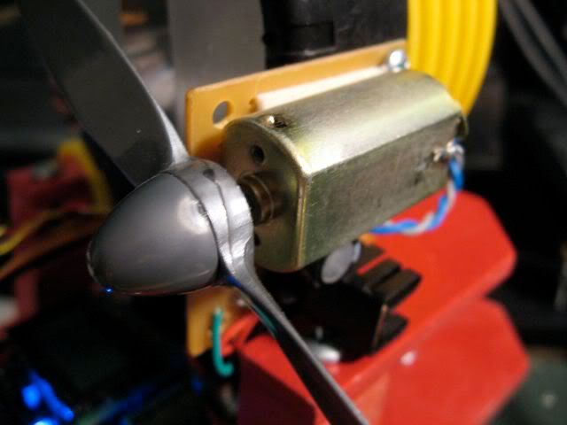
For now, I'll continue using a basic resistor which is probably good enough for steady state (operating point) analysis. I found a facsimilie of the motor I'm using. The Mabuchi FK-180SH-14800 is a 12V motor of approximately the same size that uses 0.34A at maximum efficiency. Let's say my motor uses 0.5A at 9V. In which case the motor's steady state resistance would be about 18Ω. So how do we use the TIP3055 to run this motor? (Yes, I realize that using a 15A transistor to drive a 0.5A load is overkill... it was just what I had on hand at the time)

Transistor Saturation and Topology


We want to drive the TIP3055, an NPN Bipolar Junction Transistor (BJT), into saturation. In this state, collector current, IC, is essentially at a maximum despite any additional base current, IB, that we will want to add. As you might expect, then, BJTs enter saturation mode when

IB > IC ÷ ß

Typically one wants to drive the transistor well into saturation by making sure IB is 2-10 times the saturation value of IB. This is called the overdrive factor. Ultimately, we control the amount of base current by selecting the an appropriately sized base resistor, RB.

Note that if we stick the motor on the transistor's emitter, then it limits how much extra base current we can supply at the base. Instead, it is typical practice to place the resistive load of the motor bewteen the voltage source and the collector terminal. That way the only resistance limiting IB is the base resistor.

Selecting the Base Resistor

Our first step is to determine the saturation collector current, ICsat. To do this, we analyze the circuit (right) using Kirchoff's Voltage Law where we set VBE=0: ICsat = (VCC - VCEsat) / RM ; then calculate IBsat = ICsat ÷ ß and finally, select our desired IB = 10•IBsat

The book says to assume VCEsat is approximately 0.3V. Upon looking at the data sheet for the TIP3055, actually varies depending on the IC but as long as we estimate VCEsat on the low side, it seems to me that we'd end up with a larger IB which will only ensure we are driving the transistor well into saturation.

The value of ß, as I understand it, is equal to hFE (DC current gain) for a given IC, as specified by the data sheet. Looking up an IC of 0.5A, hFE = 100. Working the numbers, we get

ICsat = (9 - 0.3) / 18 = 480mA
IBsat = 480mA ÷ 100 = 4.8mA

And with an overdrive factor of 10,

IB = 10•4.8mA = 48mA

Now that we know what IB we're looking for, we simply solve for RB = (VCC - VBE) ÷ IB. The book says to use VBE = 0.7V. We get:

RB = (9 - 0.7) ÷ 48mA = 173Ω

But I want to drive the circuit with a 5V signal from a microcontroller (the ATmega168) Hooking RB to a 5V source instead of 9V we get:

RB = (5 - 0.7) ÷ 48mA = 90Ω

SPICE Model

So let's whip up a SPICE model and see if that matches up with what we've done so far. Here's the circuit (right) with the nodes labeled. We're using a 0V supply, VM, to measure IC and similarly the 0V supply, VB, measures IB. We'll continue to use the same TIP3055 model as before and we'll set up the resistors per calculations (RB=90Ω and RM=18Ω)

This time, let's do an operating point analysis. As mentioned previously, the OP command tells SPICE to find out the steady-state of the circuit and the PRINT commands specify what variables to print. We are interested in the base voltage, V(5); the collector-emitter voltage, V(3); and of course the base current, I(VB) and collector current, I(VM).

Below is the SPICE deck to accomplish all that.
Motor driver
V9 1 0 9.0
V5 2 0 5.0
RM 1 3 18
VM 3 4 0
Q1 4 5 0 TIP3055
VB 6 5 0
RB 2 6 90

.MODEL TIP3055 NPN(Is=457.5f Xti=3 Eg=1.11 Vaf=50
+ Bf=156.7 Ise=1.346p Ne=1.34
+ Ikf=3.296 Xtb=2.2 Br=7.639 Isc=604.1f Nc=2.168
+ Ikr=8.131m Rc=91.29m Cjc=278.7p Mjc=.385 Vjc=.75
+ Fc=.5 Cje=433p Mje=.5 Vje=.75 Tr=1.412u Tf=37.34n
+ Itf=35.68 Xtf=1.163 Vtf=10 Rb=.1)
.control
op
print v(4) i(vm) v(5) i(vb)
.endc
.end
And when we run it, we get numbers that actually kind of match what we expected. Cool. Our IC is about 490 mA, IB is 47 mA and VBE is about 0.77 V. It's not exact because we were using some estimates, but it's close enough.
MacSpice 45 -> source Macintosh\ HD:Desktop:ex3.cir

Circuit: Motor driver

v(4) = 1.177197e-01
i(vm) = 4.934600e-01
v(5) = 7.675994e-01
i(vb) = 4.702667e-02
Note that the ratio of IC to IB is 10, considerably less than a ß (hFE) of 100 that we'd expect in active mode for a collector current of about 0.5A. In other words, we're forcing in extra base current without any appreciable gain in collector current. That's saturation.

Incidentally, if you want to see what happens when the 5V signal is switched off, just revise the deck to tie RB to ground. Here's what happens to the voltages and currents:
v(4) = 9.000000e+00
i(vm) = 2.201261e-11
v(5) = 9.757939e-10
i(vb) = -1.08422e-11
Base and collector current are negligible and there's no voltage drop across RM or RB. In a word, the transistor is off. Just what we expected.

Too Much Signal Current

One little gotcha. As I mentioned, I want to drive this circuit with an ATmega168 which is limited to 40mA per data pin, according to the datasheet. So in the next article I'll incorporate a second transistor to drive the first and add that to the SPICE model above and see what we can come up with.

<< [Part 1 2 3 4 5] >>

Saturday, December 22, 2007

Itsy Bitsy Spiderbot

BEAM Robotics is fundamentally about drawing inspiration from nature. I am thinking about what it would take to create a spider-like robot, using muscle wire to actuate music wire legs in a way that is similar to how a spider walks.

Then, of course, I got to fantasizing about a spider robot that could climb furniture, curtains, ... heck, walls too. Wouldn't that be cool? So then I thought to myself, "self, how do you suppose spiders can hang onto walls and whatever?" and so I brought up trusty Google and found out.

Spiders have a bunch of hairs on each foot, that branch out into finer hairs. Ultimately about 600,000 hairs per spider. These super-small hairs use the Van der Waals force of close proximity, electromagnetic attraction between atoms -- like some kind of atomic nano-Velcro.

So, all I have to do is create several hundred thousand ultra microscopic hairs and glue them one by one onto some kind of foot...