 |
| Test rig for current measurement |
Data Bus was cursed by Compass heading deflection earlier this year and I never discovered its cause. The error observed was on the order of 20 degrees or more.
As part of my ongoing work to get ready for the just-announced Sparkfun AVC 2012, I want to see if I can correlate motor current and magnetometer readings using a Honeywell HMC5843 3-axis magnetometer.
The Experiment
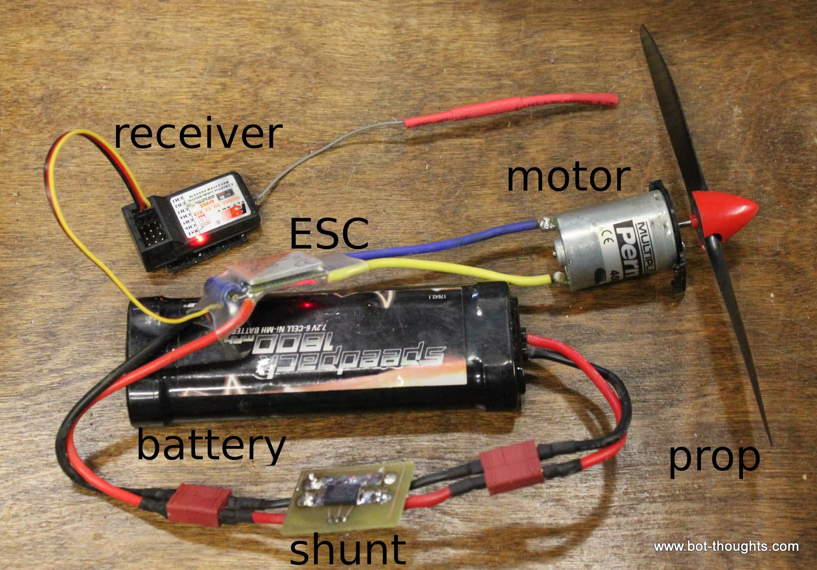 |
| Test rig for measuring motor current. |
The values from the magnetometer were read by Data Bus' mbed microcontroller and printed over serial. I used a DMM to measure current while capturing X, Y and Z magnetic readings from the sensor for a range of current values.
Initially I used a 6V Speed 400, 380 brushed motor with a 7x3 propeller which drew on the order of 9A max. To measure the effects of higher current, I used Data Bus' original 20T, 540 brushed motor with a larger prop and was easily able to draw over 20A of current. Neither motor was equipped with a flux ring.
In the first test I used the 1800mAH NiMH battery pictured above, except on the 8A test where I switched to a 2200mAH 2S 25C Gens Ace LiPo. I continued to use that battery for the larger motor tests along with a bigger 30A SIG ESC.
Data Plots
The results of the first two tests are in. The plot below shows magnetometer effects for the smaller motor with ampere draws in the 0 through 8A range. Effects on 2D heading calculation are shown, too.

The 2D heading varied by less than half a degree between the 0A and 8A readings. Below is the plot for the bigger motor and ampere draws from 0 to 22A. Effects on 2D heading calculation are shown again.

The 2D heading varied by just over half a degree.
Conclusion
As expected, motor current appears to correlate with changes to magnetometer readings; however, the effect is minimal. The calculated heading suffers only minor error even up to 22A for a 540 size, 20T brushed motor with no shielding (flux ring), and at a distance of only 5.25" between motor and sensor.
As magnetic fields diminish with the cube of the distance, even a slight increase in distance should reduce the already minor effects to negligible levels.
The cause of the observed compass errors, it appears, is to be found elsewhere...
Hmm, I was concerned about that as well, but half a degree seems pretty minimal. I'll recreate your experiment with the brushless motors I plan to use with the T1 robot in a couple of weeks.
ReplyDelete